Welding source output control method

A welding power source and output control technology, applied in welding equipment, manufacturing tools, arc welding equipment, etc., can solve the problems of unable to reduce output, long arc period, etc.

Active Publication Date: 2014-02-12
DAIHEN CORP
View PDF7 Cites 8 Cited by
  • Summary
  • Abstract
  • Description
  • Claims
  • Application Information

AI Technical Summary

Problems solved by technology

Of course, the arc period is shorter than when the output cannot be lowered when the predetermined peri

Method used


Image

  • Welding source output control method
  • Welding source output control method
  • Welding source output control method

Examples


Embodiment approach 1

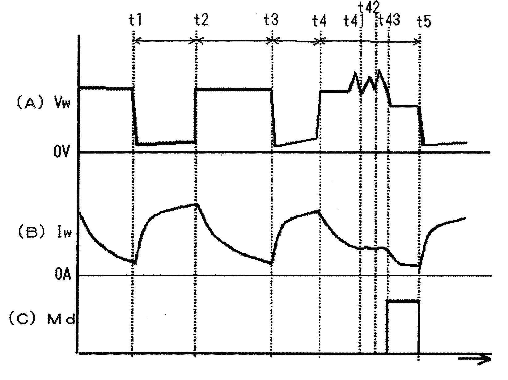
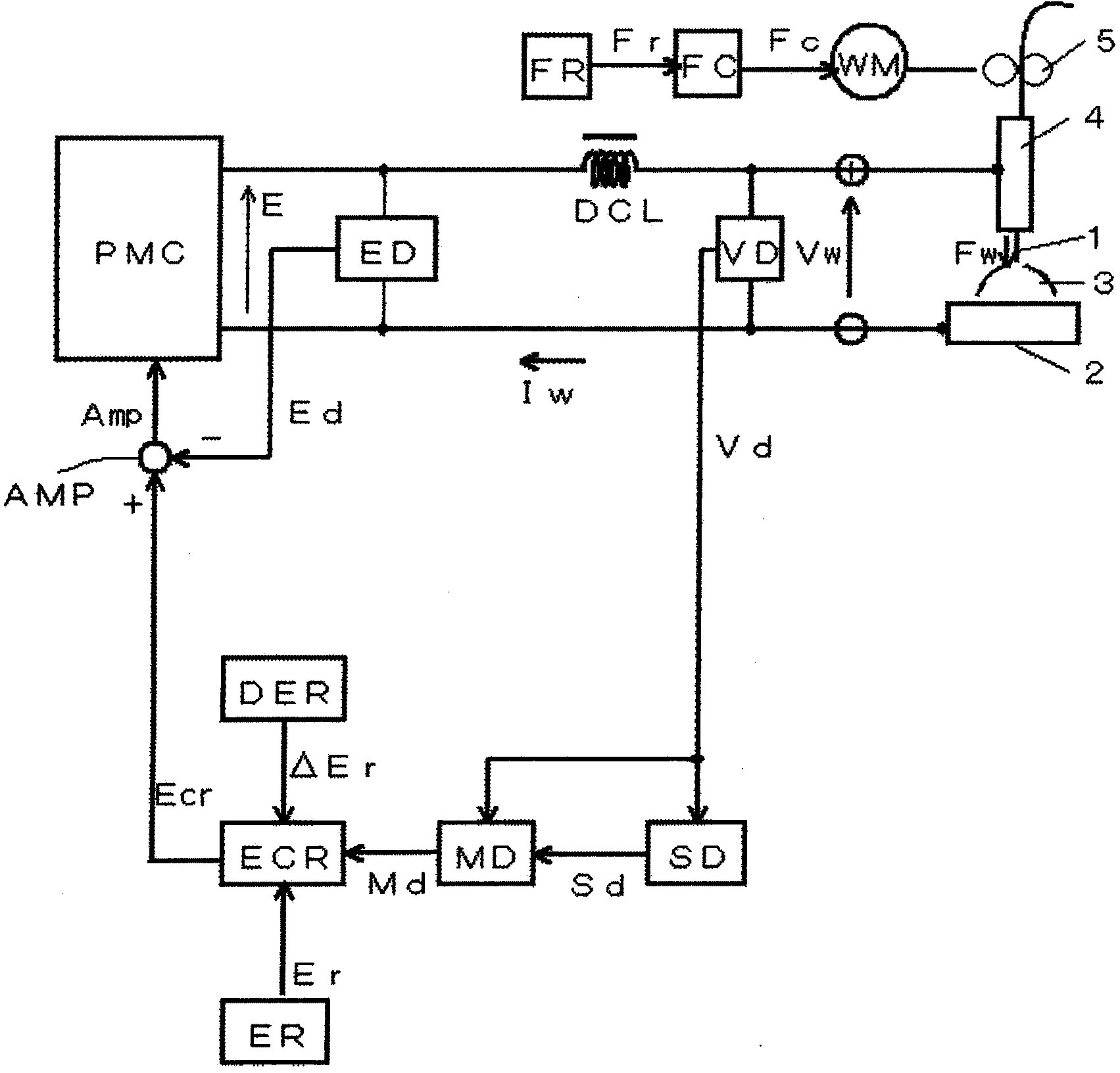
[0062] figure 1 It is a voltage / current waveform diagram which shows the output control method of the welding power supply concerning Embodiment 1 of this invention. figure 1 (A) represents the waveform of the welding voltage Vw, figure 1 (B) represents the waveform of the welding current Iw, figure 1 (C) shows the waveform of the droplet state determination signal Md. figure 1 corresponding to the above Figure 5 , is the case of carbon dioxide arc welding with an average welding current of 230A. figure 1 Indicates a 2-cycle waveform. During the period from time t1 to t3, there is no gas ejection from the molten pool, and the welding state is stable, and during the period from time t3 to t5, gas ejection from the molten pool occurs. The above-mentioned droplet state determination signal Md is a signal that becomes High level when it is determined that the droplet is in a state of being pushed upward. exist figure 1 In , the feeding speed of the welding wire is al...

Embodiment approach 2

[0080] In the invention of the second embodiment, the feeding speed of the welding wire is increased in synchronization with the reduction of the welding current of the first embodiment.

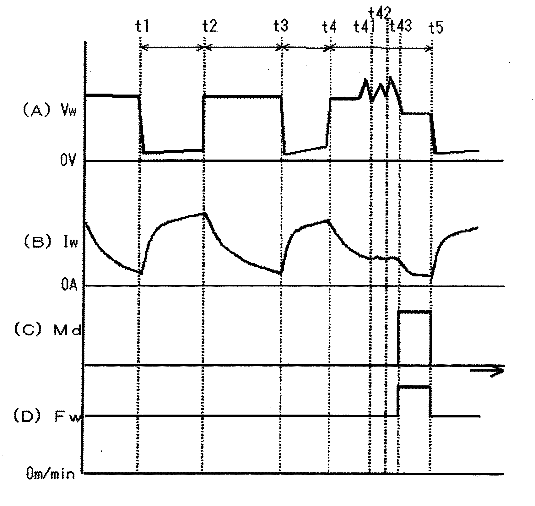
[0081] image 3 It is a voltage / current waveform diagram which shows the output control method of the welding power supply concerning Embodiment 2 of this invention. image 3 (A) represents the waveform of the welding voltage Vw, image 3 (B) represents the waveform of the welding current Iw, image 3 (C) shows the waveform of the droplet state determination signal Md, image 3 (D) shows the waveform of the feed rate Fw. image 3 It is carbon dioxide arc welding with an average welding current of 230A. image 3 Indicates a 2-cycle waveform. During the period from time t1 to t3, there is no gas ejection from the molten pool, so the welding state is stable, and gas ejection from the molten pool occurs during the period from time t3 to t5. image 3 corresponding to the above figure 1 , ...


PUM


Abstract

The invention provides a welding source output control method which suppresses the prolonging of electric arc period caused by the spray out of gases from a weld pool during the carbon dioxide electric arc welding. The welding source output control method controls the output of the welding source, which is used for the electric arc welding during the repeated short circuit period and the electric arc period between a welding wire and a base metal, through the feedback control of the welding voltage. During the electric arc period of t3-t5, the variation of the welding voltage (Vw) repeatedly exceeds the preset reference valve more than twice (t41, t42, and t43), the welding current (Iw) is reduced to the starting time (t5) of a next short circuit period. Therefore, the welding current (Iw) is immediately reduced when the spray out of gases is determined, so that the prolonging the electric arc period can be suppressed and the increasing of sputtering generation can be prevented.

Description

technical field [0001] The present invention relates to an output control method of a welding power source used in short-circuit arc welding, and more particularly to an output control method for suppressing instability of a droplet transfer state due to gas ejection from a molten pool. Background technique [0002] In short-circuit arc welding in which the short-circuit period and the arc period are repeated between the wire and the base metal, it is important to reduce and stabilize the variation in the cycle combining the short-circuit period and the arc period in order to ensure good welding quality. A reasonable value for this period varies with the average welding current (feed rate). When the average welding current is about 150A, the cycle is about 10ms, when the average welding current is about 200A, the cycle is about 20ms, and when the average welding current is about 250A, the cycle is about 40ms. The short-circuit arc welding described above includes, in additi...

Claims


Application Information

Patent Timeline
IPC IPC(8): B23K9/073B23K9/16
CPCB23K9/0953B23K9/1012B23K9/0732B23K9/0734B23K9/095B23K9/124
Inventor 井手章博
Owner DAIHEN CORP
Why Eureka
Try Eureka