Multicolor injection molding machine

An injection molding machine and frame technology, applied in the field of multi-color injection molding machines, can solve the problems of low injection efficiency, and achieve the effects of reliable use, fast clamping and compact structure

Inactive Publication Date: 2014-02-12
ZHANGJIAGANG XINXIN MOLDING
View PDF4 Cites 3 Cited by
  • Summary
  • Abstract
  • Description
  • Claims
  • Application Information

AI Technical Summary

Problems solved by technology

The main problem of the injection molding machine with this structure is: the intermediate rotating part carrying the injection molded parts is always near the injection port of the injection molding machine. Since the injection molding temperature is mostly between 160°C and 200°C, the temperature near the injection port is relatively high, and the injection molded parts need to It takes a long time for cooling and molding to enter the injection molding of the next station. The time required for each mold is about 70 seconds, and the injection molding efficiency of the whole machine is low.

Method used


Image

  • Multicolor injection molding machine
  • Multicolor injection molding machine
  • Multicolor injection molding machine

Examples


Embodiment 1

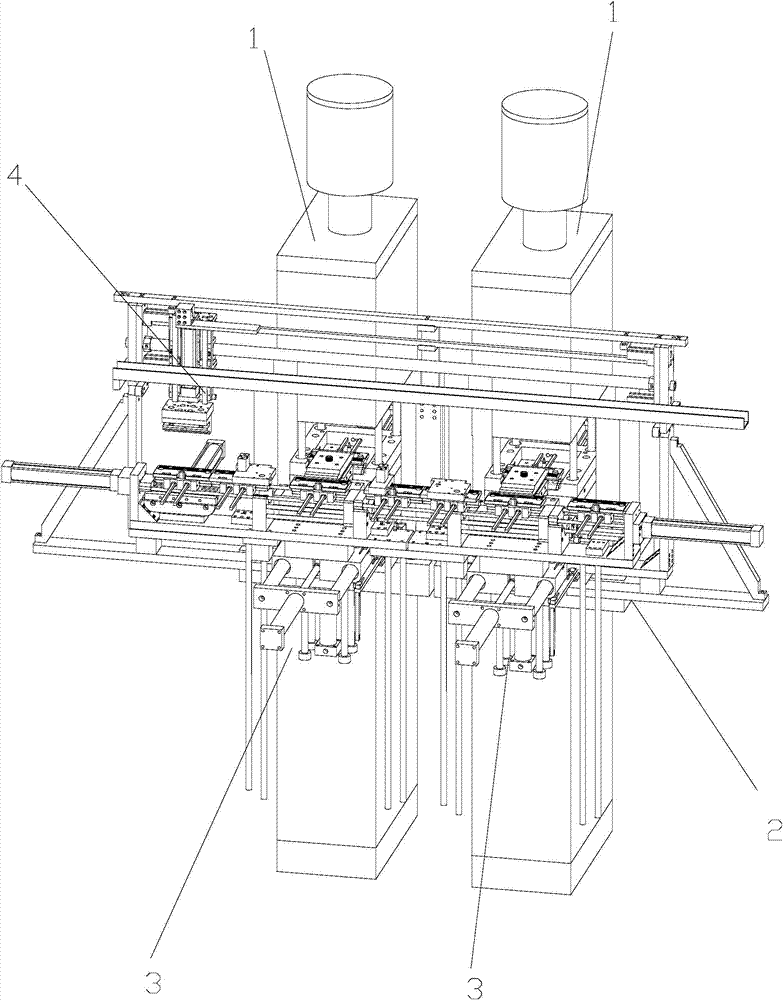
[0034] Example 1 as Figure 1-4 As shown, a multi-color injection molding machine includes a frame 2 and at least two injection molding machines 1 for injection molding. The injection molding machines 1 are arranged side by side, and each injection molding machine 1 is equipped with a workpiece on the frame 2 The clamping device 3 is also provided with a workpiece transmission mechanism 4 on the frame.

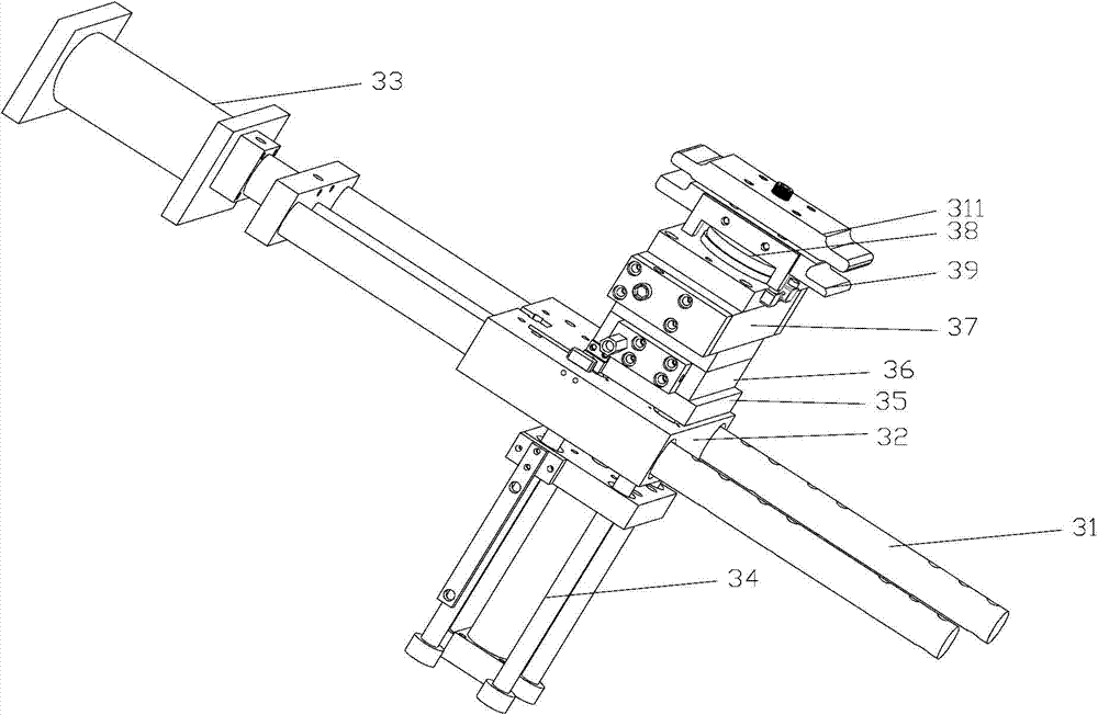
[0035] The workpiece clamping device 3 includes a slide rail 31 arranged on the frame 2 , a base 32 is arranged on the slide rail 31 , and the side of the base 32 is connected with a pushing cylinder 33 arranged on the frame 2 . A shield is provided on the frame 2 at the position where the pushing cylinder 33 pushes the base 32 to move. The lower surface of the base 32 is provided with a lift cylinder 34, and the piston 375 rod of the lift cylinder 34 passes through the base 32 and is provided with a mounting seat 35 thereon. The lower surface of the mounting seat 35 is prov...

Embodiment 2

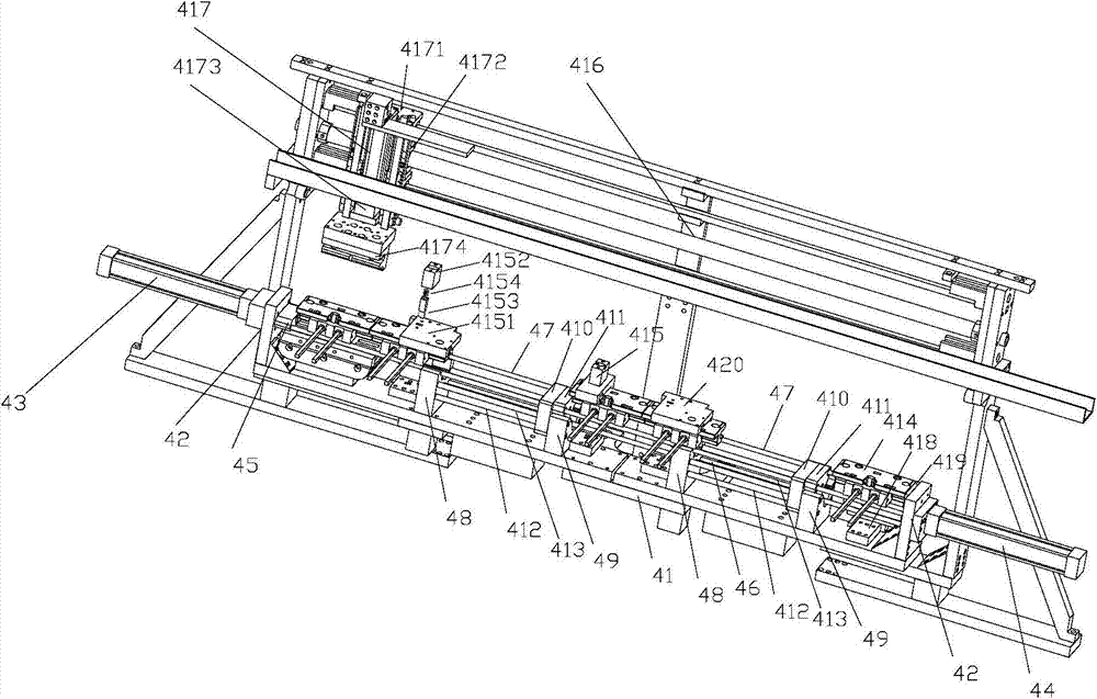
[0055] Example 2 as Figure 3-6 As shown, it is a five-station injection molding machine, which is different from Embodiment 1 in that it includes five injection molding machines 1, and the transmission mechanism 4 is correspondingly provided with five working stations.

Embodiment 3

[0056]Example 3 as image 3 , 4 , 7, and 8 show that the five-station injection molding machine is used for three-color injection molding processing. The multi-color injection molding machine also includes five working stations. The side is provided with a tail block 419, and the round-trip stroke of the transmission trolley 417 is also adjusted to a corresponding length, so as to be used to complete the processing of three-color injection molding products.


PUM


Abstract

The invention discloses a multicolor injection molding machine which is short in cooling time required by an injection molding member and high in injection molding efficiency. The multicolor injection molding machine comprises at least two injection molding machine platforms; a conveying mechanism comprises a base, side plates are arranged at two ends of the base, a left drive oil cylinder and a right drive oil cylinder are respectively arranged on the outer sides of the two side plats, a left drive block is arranged at the end part of a piston rod of the left drive oil cylinder, a drive rod is connected to the end part of a piston rod of the right drive oil cylinder, two sliding rods are arranged between the side plates, a starting station, a plurality of working stations arranged at intervals and an ending station are arranged on the sliding rods from left to right, a left locating block, a right locating block, a left sliding block and a right sliding block are arranged on each working station on the base, the drive rod penetrates through each left locating block, each locating block, each left sliding block and each right sliding block, the left sliding blocks and the right sliding blocks move to the left locating blocks when the piston rod of the right drive oil cylinder is pushed out, and the left sliding blocks and the right sliding blocks move to the right locating blocks when the piston rod of the right drive oil cylinder is retracted.

Description

technical field [0001] The invention relates to a multi-color injection molding machine. Background technique [0002] There are many multi-color injection molding machines common in the market, as described in the patent No. ZL201220212022.0 titled "Three-station Mold for Three-color Injection Molding Machine". An intermediate rotating part. The product to be injected or the core mold is set on the intermediate rotating part. The intermediate rotating part is rotated to the injection station of different colors to complete the injection molding of various colors. The main problem of the injection molding machine with this structure is: the intermediate rotating part carrying the injection molded parts is always near the injection port of the injection molding machine. Since the injection molding temperature is mostly between 160°C and 200°C, the temperature near the injection port is relatively high, and the injection molded parts need to It takes a long time for cooling a...

Claims


Application Information

Patent Timeline
Patent Type & Authority Applications(China)
IPC IPC(8): B29C45/16B29C45/42B29C31/00
CPCB29C45/13B29C45/16B29C45/162B29C2045/1621
Inventor 戴益新
Owner ZHANGJIAGANG XINXIN MOLDING
Why Eureka
Try Eureka