Torsion beam assembly

A technology of torsion beam and assembly, applied in interconnection systems, suspension, transportation and packaging, etc., can solve the problems of torsion beam failure, stress concentration, torsion beam failure, etc., to reduce torsional force and reduce torsional deformation. Effect

Inactive Publication Date: 2014-02-12
SAIC-GM-WULING AUTOMOBILE CO LTD
View PDF4 Cites 3 Cited by
  • Summary
  • Abstract
  • Description
  • Claims
  • Application Information

AI Technical Summary

Problems solved by technology

For example, if the structural design margin of the longitudinal arm 102 and the beam 101 is insufficient or the quality of the weld is slightly poor, cracks are likely to occur in the structurally weak areas 104 such as the weld and its vicinity, and under the action of alternating stress, the rapid expansion of the weld causes torsional force Beam failure, in severe cases, the torsion beam fails, affecting the driving safety of the car
[0006] 2) When the left / right wheels bounce asymmetrically due to road conditions, the crossbeam 101 is twisted and deformed. Since the spring seat 103 overlaps the crossbeam 101, the spring seat 103 twists and deforms along with the crossbeam 101, causing the spring seat 103 to contact the crossbeam. 101 Stress concentration in welding area 105, cracking is easy to occur when the design margin is insufficient or the quality of the weld is poor. In severe cases, the torsion beam fails, which affects the driving safety of the car

Method used


Image

  • Torsion beam assembly
  • Torsion beam assembly
  • Torsion beam assembly

Examples


Embodiment Construction

[0019] The present invention will be further described below in conjunction with the accompanying drawings and specific embodiments.

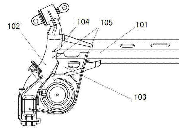
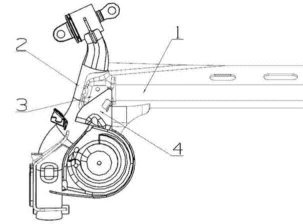
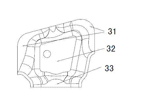
[0020] Figure 2 to Figure 4 The reference numerals in the figure are: beam 1; longitudinal arm 2; reinforced cover plate 3; first welded reinforcement flange 31; 7, 8.

[0021] The purpose of the present invention is to provide a torsion beam assembly to protect the weld seam between the beam and the longitudinal arm, increase the rigidity of both ends of the beam, and significantly reduce the stress of the welding area of ​​the beam and the longitudinal arm and the edge of the beam near the beam during use, which can be used for Automotive torsion beam suspension.

[0022] like Figure 2 to Figure 4 As shown, a torsion beam assembly includes a spring seat 4, a crossbeam 1 and a longitudinal arm 2. The torsion beam assembly also includes a reinforcement cover 3, and the reinforcement cover 3 is connected to the crossbeam 1 and the longitudi...


PUM


Abstract

The invention provides a torsion beam assembly which comprises a spring base, a transverse beam and a longitudinal arm. The torsion beam assembly further comprises a reinforcing cover plate, the reinforcing cover plate is respectively connected with the transverse beam and the longitudinal arm, and the spring base is arranged on the reinforcing cover plate. The torsion beam assembly has the advantages that connecting strength of the transverse beam and the longitudinal beam can be enhanced through the reinforcing cover plate, the spring base can be arranged on the reinforcing cover plate, force is prevented from being directly transmitted to the transverse beam from the spring base, torsional force of the transverse beam is decreased, and torsion deformation of the transverse beam is reduced.

Description

technical field [0001] The invention relates to a torsion beam assembly, in particular to a torsion beam assembly used in a torsion beam semi-independent suspension system. Background technique [0002] The torsion beam semi-independent suspension is the commonly used rear suspension structure of automobiles at present. It has the advantages of simple structure, low cost and small space occupation. The trailing arm is welded together, the front end of the trailing arm is connected with the body through rubber-metal support, and the rear end of the trailing arm is connected with the wheel hub, shock absorber and spring. The longitudinal arm of the torsion beam can swing up and down around the rubber hinge point to absorb vibration through the shock absorber and spring. When the deformation of the suspension on both sides is unequal, the torsion beam will twist and deform, which can play the role of a lateral stabilizer. The torsion beam assembly is the key component of the t...

Claims


Application Information

Patent Timeline
Patent Type & Authority Applications(China)
IPC IPC(8): B60G21/055
Inventor 潘俊斌韦友超鄢长文胡少君
Owner SAIC-GM-WULING AUTOMOBILE CO LTD
Why Eureka
Try Eureka