
Frequency conversion, speed regulation and comprehensive electrical control system for electric locomotive

An electrical control system and frequency conversion speed regulation technology, which is applied to locomotives and other directions, can solve the problems of low starting traction performance, long shutdown time, large starting impact, etc., and achieve the effect of perfecting protection function, saving electric energy and improving starting efficiency.

Inactive Publication Date: 2014-02-12
宜昌兆峰自动化仪表有限责任公司
View PDF0 Cites 3 Cited by
  • Summary
  • Abstract
  • Description
  • Claims
  • Application Information

AI Technical Summary

Problems solved by technology

Because the traditional energy-consumption braking uses resistance to absorb energy to achieve control, the starting impact is large, the mechanical loss is high, and the single-mechanical brake is used for step-wise speed regulation. In terms of energy consumption, the resistance speed regulation method consumes less energy high
The use of chopper speed regulation can save 30% of energy consumption. Taking the resistance speed controller as an example, the braking type is a single mechanical brake, the speed regulation method is stepped speed regulation without a given method, and the starting traction performance is low. Large start-up impact, large mechanical wear, high failure rate, no-current braking mode, arc on-off, resulting in frequent maintenance, production shutdown, and long time delays

Method used


Image

  • Frequency conversion, speed regulation and comprehensive electrical control system for electric locomotive
  • Frequency conversion, speed regulation and comprehensive electrical control system for electric locomotive
  • Frequency conversion, speed regulation and comprehensive electrical control system for electric locomotive

Examples


Embodiment Construction

[0022] Embodiments of the present invention will be further described below in conjunction with the accompanying drawings.

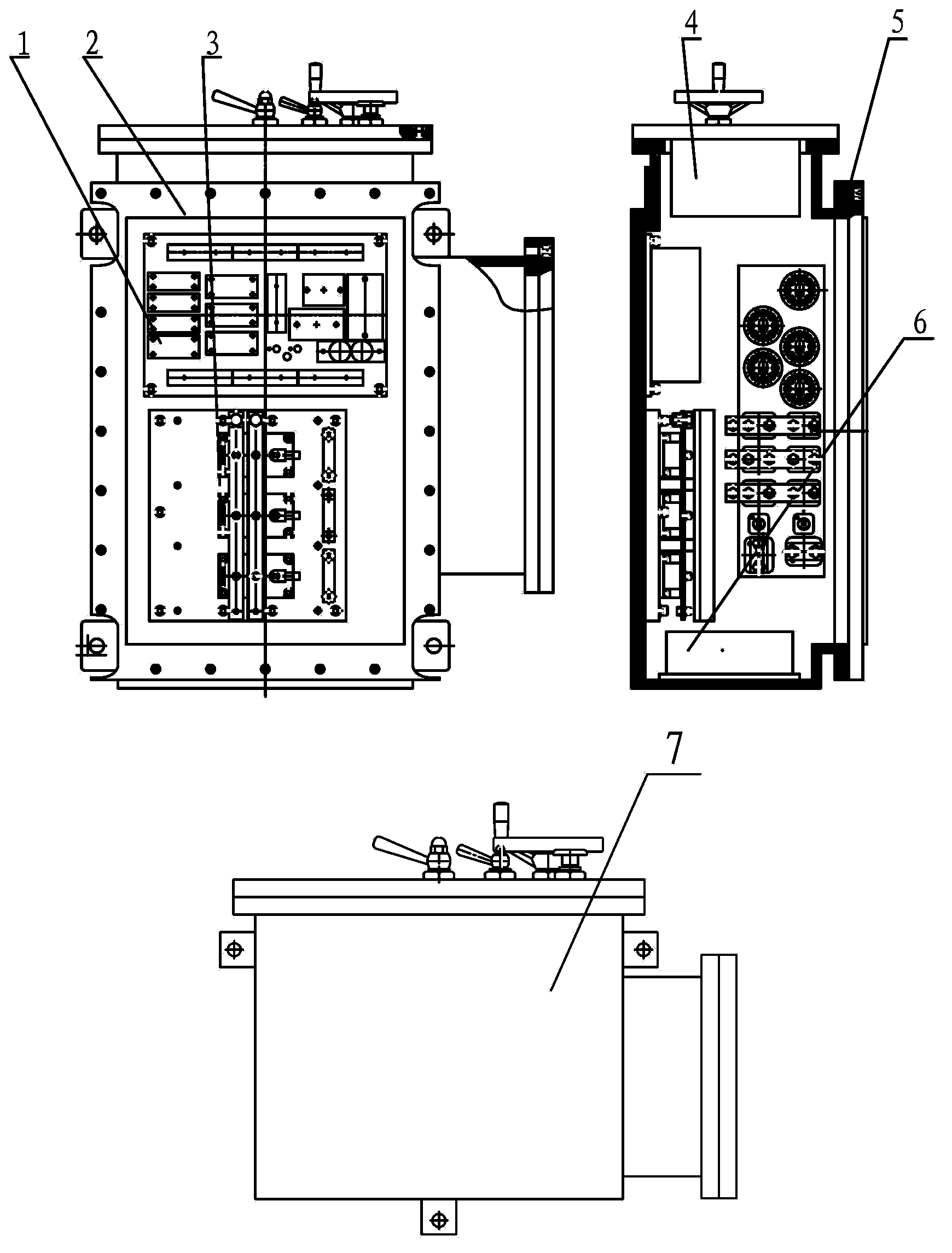
[0023] The structure diagram of the main engine of the frequency conversion and speed regulation integrated electrical control system of the electric locomotive is as follows: figure 1 shown. The control system includes a control electrical assembly board 1 , a main cavity assembly 2 , a frequency conversion system assembly 3 , a control operating system assembly 4 , a main cover assembly 5 , and a power assembly board 6 . like figure 1 As shown, first install the control electrical summary board 1 and the frequency conversion system assembly 3 on the main cavity assembly 2 through mounting screws. After the above process is completely and correctly installed, install the main cover assembly 5 and the control operating system assembly 4. On main chamber assembly 2.

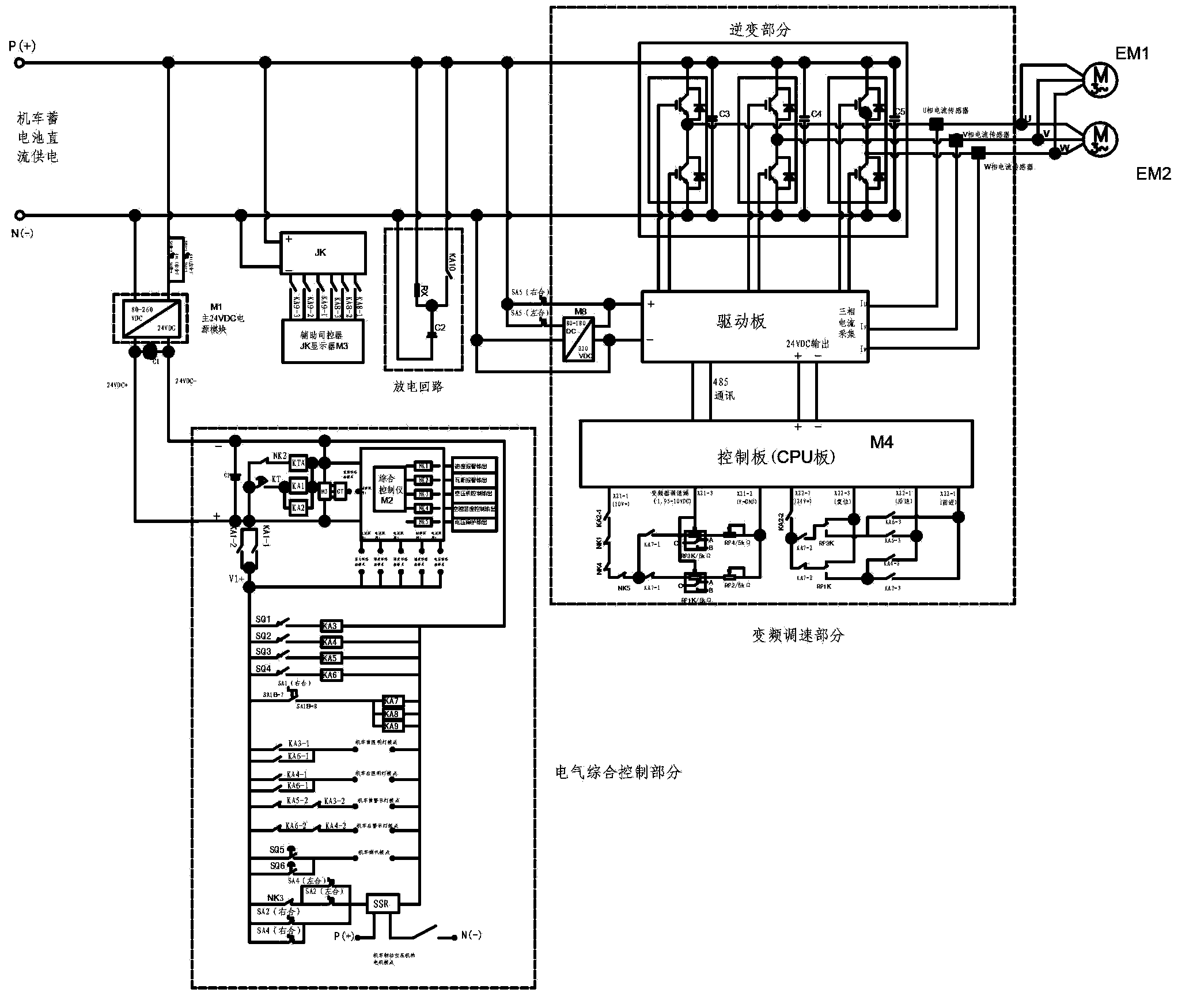
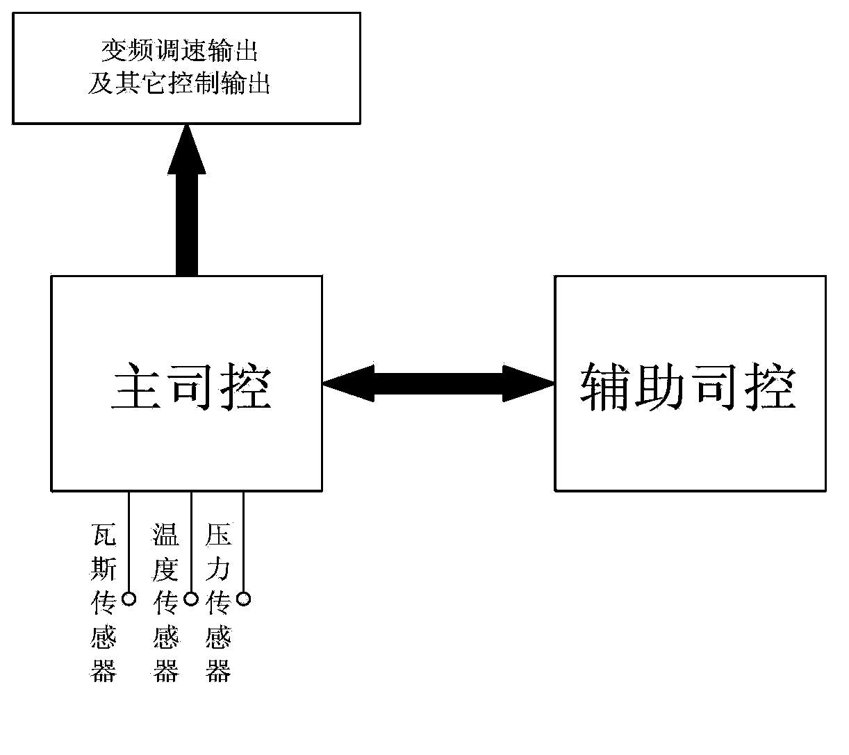
[0024] The working principle of the control system is shown in the figure 2 shown. ...


PUM


Abstract

The invention provides a frequency conversion, speed regulation and comprehensive electrical control system for an electric locomotive. The control system comprises a control electrical collection plate, a main cavity assembling member, a frequency conversion combiner, a driver controlled operating system assembly, a main cover plate assembling member, a power supply collection plate and an auxiliary driver controller. The control system is applicable to frequency conversion, speed regulation and comprehensive electrical control of an underground coal mine storage battery locomotive and comprises inverted frequency conversion and speed regulation, driver control, comprehensive monitoring of storage batteries, pressure and temperature control of air compressors, speed detection control, gas monitoring control and comprehensive control of locomotive lamps, loudspeakers and the like. The control system is small in volume, high in integration degree, safe and reliable, and simple to operate.

Description

technical field [0001] The invention relates to the technical field of electrical control of electric locomotives powered by storage batteries, in particular to an integrated electrical control system for frequency conversion and speed regulation of electric locomotives. Background technique [0002] At present, the existing battery-powered electric locomotive controllers mainly have two types: one is to use resistance current limiting to realize energy-consumption braking of electric locomotive speed regulation, and the other is to use high-power electronic components to drive, and their speed The speed is adjusted by IGBT chopping. Because the traditional energy-consumption braking uses resistance to absorb energy to achieve control, the starting impact is large, the mechanical loss is high, and the single-mechanical brake is used for step-wise speed regulation. In terms of energy consumption, the resistance speed regulation method consumes less high. The use of chopper ...

Claims


Application Information

Patent Timeline
Patent Type & Authority Applications(China)
IPC IPC(8): B61C17/12
Inventor 熊章华张兆峰
Owner 宜昌兆峰自动化仪表有限责任公司
Learn More