
Rotor composite yarn spinning device

A composite yarn and rotor technology, which is applied in spinning machines, open-end spinning machines, and continuously wound spinning machines, etc., can solve the problem that the fiber strength cannot be fully utilized, and the appearance and strength of rotor spinning yarns are affected. problems, to achieve the effect of increasing aesthetics, reducing the formation of straddling fibers, and enhancing stability

Inactive Publication Date: 2014-02-12
ZHEJIANG SCI-TECH UNIV
View PDF8 Cites 7 Cited by
  • Summary
  • Abstract
  • Description
  • Claims
  • Application Information

AI Technical Summary

Problems solved by technology

Wound fibers are reversely and irregularly wound on the surface of the sliver, and the strength of the fibers cannot be fully utilized, thus affecting the appearance and strength of the rotor spun yarn

Method used


Image

  • Rotor composite yarn spinning device
  • Rotor composite yarn spinning device
  • Rotor composite yarn spinning device

Examples


Embodiment Construction

[0021] The present invention will be further described below in conjunction with the accompanying drawings and embodiments.

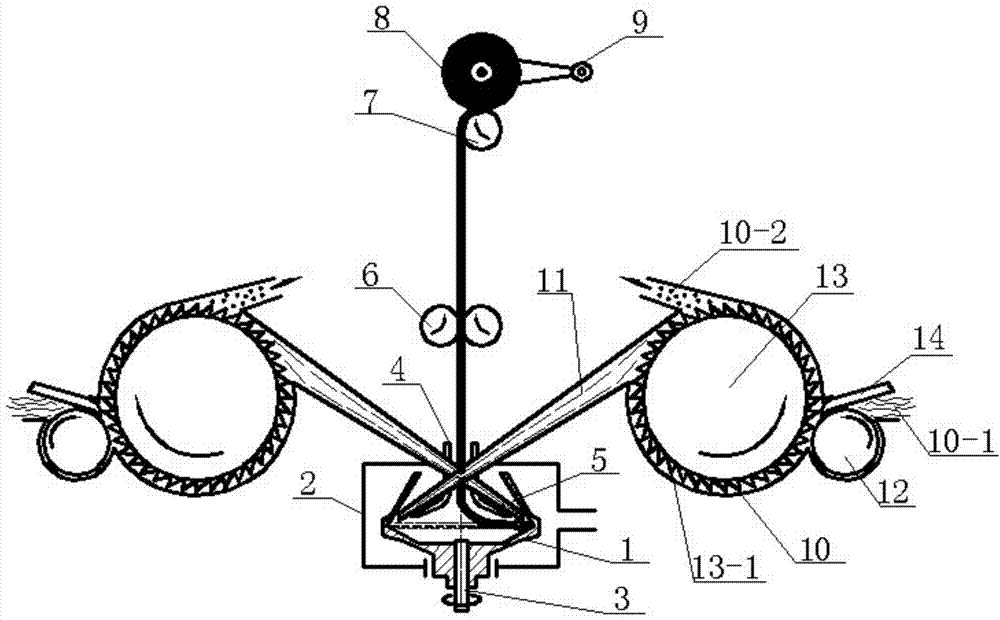
[0022] Such as figure 1 As shown, a rotor composite yarn spinning device includes a cohesive twisting mechanism, a winding forming mechanism, and a feeding and carding mechanism; two feeding and carding mechanisms are symmetrically arranged on both sides of the cohesive and twisting mechanism.

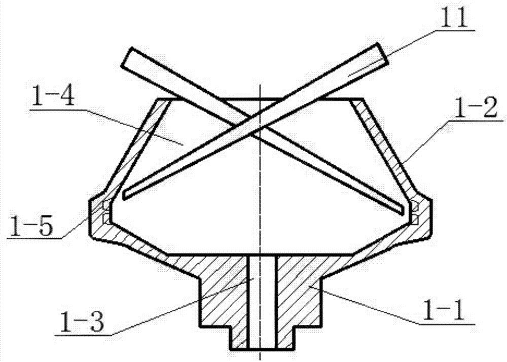
[0023] Such as figure 1 and 2 As shown, the cohesive twisting mechanism includes a spinning cup 1, an air suction device 2, a guide tube 3, a yarn guide tube 4 and a twist disc 5. The spinning cup 1 includes a cup holder 1-1 and a cup body 1-2 which are integrally formed and arranged coaxially. The cup holder 1-1 is arranged at the bottom of the cup body 1-2; The wire pipe installation hole 1-3; the upper part of the cup body 1-2 is an upright truncated cone shape, and the lower part is an inverted truncated cone shape, and a cavity 1-4 consistent with the sh...


PUM


Abstract

The invention discloses a rotor composite yarn spinning device. An air extracting type spinning cup on an existing rotor yarn spinning machine can be easily abraded, and winding fibers can be easily generated during a spinning process. According to the rotor composite yarn spinning device, two feeding carding mechanisms are symmetrically arranged on the two sides of a condensation twisting mechanism, two ring-shaped condensation grooves are formed in a spinning cup, a filament guiding pipe and the spinning cup are fixed, a yarn guiding pipe and an air extracting device are fixed, a twisting stopping disc and the yarn guiding pipe are fixed, feeding openings are formed in the outer sides of the shell bodies of the two feeding carding mechanisms, the inner sides of the shell bodies of the two feeding carding mechanisms are respectively communicated with one end of a fiber conveying pipe, the other ends of the two fiber conveying pipes extend into the spinning cup, impurity discharging openings are formed in the portions, close to the corresponding fiber conveying pipes, of the two shell bodies, feeding rollers and the carding rollers are arranged in the shell bodies, the feeding rollers are arranged at the feeding openings, and feeding plates are arranged between the feeding rollers and the shell bodies. According to the rotor composite yarn spinning device, the types of the composite yarn which can be spun by a rotor yarn spinning machine can be increased, the winding fibers can be prevented from being generated, and yarn strength is improved.

Description

technical field [0001] The invention belongs to the field of spinning equipment, relates to a rotor spinning machine, in particular to a rotor composite yarn spinning device. Background technique [0002] Among the new spinning methods, rotor spinning has become a spinning method with a wide range of applications due to its mature technology and good economic benefits. Due to the unique spinning principle and equipment structure completely different from ring spinning, rotor spinning has obvious advantages: high speed, large output, up to 150,000 rpm, large package capacity, simple process, It is suitable for spinning more raw materials and lower cost. [0003] With the continuous development of society, consumers have more and more demand for personalized products and differentiated products. This differentiated market demand has become the driving force to promote the development of differentiated products in the textile industry. In order to meet the needs of the market...

Claims


Application Information

Patent Timeline
Patent Type & Authority Applications(China)
IPC IPC(8): D01H4/08D01H4/10
Inventor 肖美娜窦华书
Owner ZHEJIANG SCI-TECH UNIV
Learn More