Manual draining device
A dewatering machine, an integrated technology, which is used in drying machines, textiles and papermaking, household appliances, etc., can solve the problems of poor running stability, difficult to control the coaxiality of the shaft and the shaft sleeve, and large vibration, and achieves improved rigidity and vibration. Small, good vibration reduction and noise reduction effect
- Summary
- Abstract
- Description
- Claims
- Application Information
AI Technical Summary
Problems solved by technology
Method used
Image

Examples
Embodiment 1
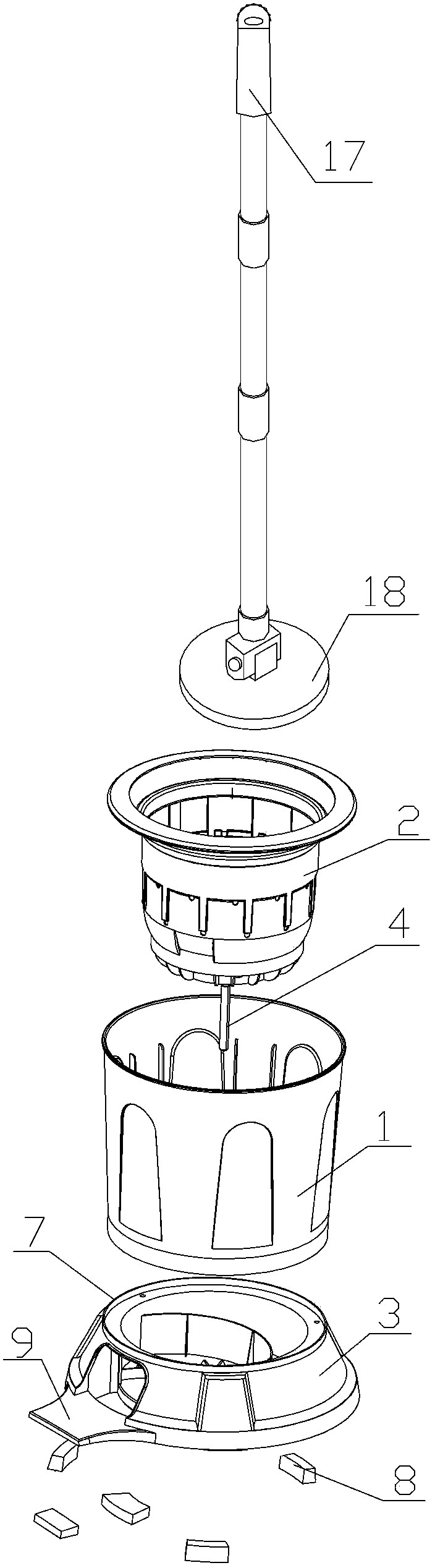
[0025] Such as figure 1 As shown, a manual dehydrator includes an outer barrel 1, an inner barrel 2 and a base 3, the inner barrel 2 is rotatably sleeved inside the outer barrel 1, and the outer barrel 1 is fixedly mounted on the base 3 by a plurality of screws. When working, the clothes to be dehydrated are placed in the inner tub 2, and the inner tub 2 is rotated at a high speed by a manual mechanism to generate centrifugal force to dry the clothes in the inner tub 2.
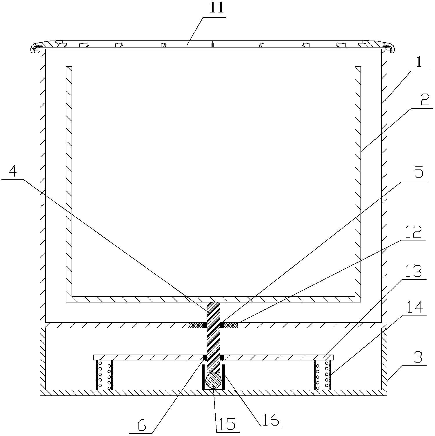
[0026] Such as figure 2 As shown, in order to ensure the smooth rotation of the inner barrel 2, a shaft 4 is connected to the bottom of the inner barrel 2, and the other end of the shaft 4 passes through the bottom of the outer barrel 1 and is connected to the base 3. In order to ensure the coaxiality and stability of the shaft 4, In order to realize the smooth operation of the machine during the dehydration process and reduce the vibration, two sleeves for supporting the rotation of the shaft 4 are sequent...
Embodiment 2
[0039] The difference from Embodiment 1 is that, as Figure 4As shown, in order to ensure the smooth rotation of the inner barrel 2, a shaft 4 is connected to the bottom of the inner barrel 2, and the other end of the shaft 4 passes through the bottom of the outer barrel 1 and is connected to the base 3, and the outer barrel 1 and the base 3 are sequentially provided with two The shaft sleeves used to support the rotation of the shaft 4 are respectively the first shaft sleeve 5 and the second shaft sleeve 6 .
[0040] like Figure 4 As shown, the first shaft sleeve 5 is arranged on the bottom wall of the tub 1 , and the shaft 4 passes through the first shaft sleeve 5 and rotates in the first shaft sleeve 5 . The second shaft sleeve 6 is directly arranged on the base 3 , and the bottom end of the shaft 4 is inserted into the second shaft sleeve 6 and rotates in the second shaft sleeve 6 .
[0041] In this embodiment, preferably, the shaft 4 is integrally formed with the inner...
Embodiment 3
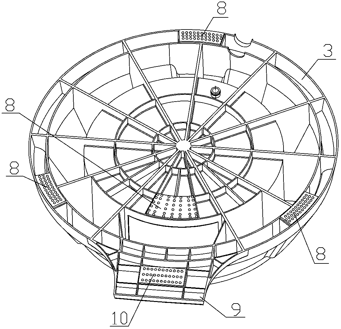
[0044] The difference from the first and second embodiments above is that the pedal 9 arranged on one side of the base 3 is used as a part of the manual mechanism, and the manual mechanism also includes a set of rack and pinion transmission mechanisms connected with the pedal 9 (in the figure not shown), the pedal 9 is connected to a rack, the rack is meshed with a gear, and the gear and the shaft 4 are connected by a key. The gear rotates, and then the gear drives the shaft 4 and the inner tub 2 to rotate. In order to increase the rotating speed of the inner barrel 2, the gear transmission can adopt a transmission mode in which a plurality of large gears and small gears cooperate.
PUM
 Abstract
Description
Claims
Application Information
 - R&D
- Intellectual Property
- Life Sciences
- Materials
- Tech Scout
- Unparalleled Data Quality
- Higher Quality Content
- 60% Fewer Hallucinations
Browse by: Latest US Patents, China's latest patents, Technical Efficacy Thesaurus, Application Domain, Technology Topic, Popular Technical Reports.
© 2025 PatSnap. All rights reserved.Legal|Privacy policy|Modern Slavery Act Transparency Statement|Sitemap|About US| Contact US: help@patsnap.com