Valve

A technology for valve elements and loading valves, which is applied in the field of valves, can solve the problems of large valve shells, etc., and achieve the effects of reducing volume, simplifying space, and reducing manufacturing and assembly costs

Inactive Publication Date: 2014-02-12
ALFMEIER PRAZISION BAUGRUPPEN & SYSTLOSUNGEN
View PDF6 Cites 5 Cited by
  • Summary
  • Abstract
  • Description
  • Claims
  • Application Information

AI Technical Summary

Problems solved by technology

Due to the space required for the printed circuit board, the housing of the valve is correspondingly bulky, which is disadvantageous when installing the valve in tight spaces

Method used


Image

  • Valve
  • Valve
  • Valve

Examples


Embodiment Construction

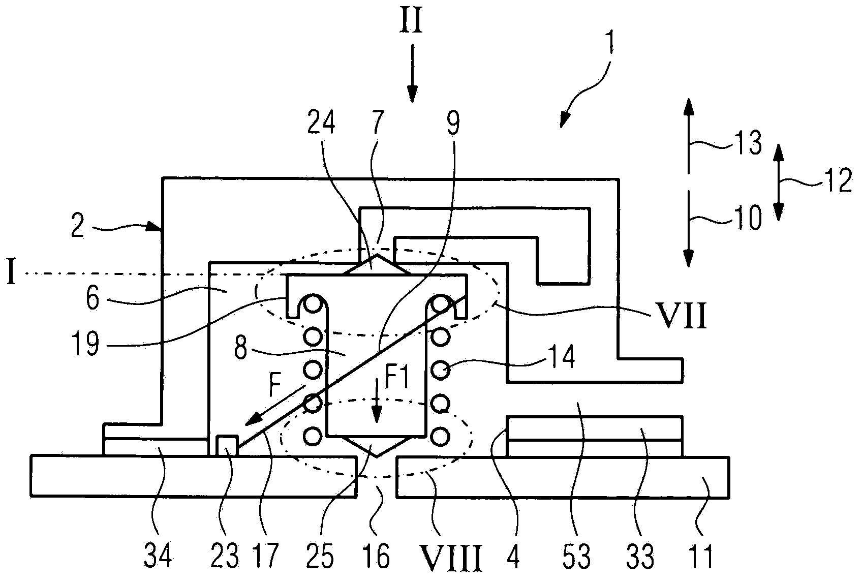
[0017] in Figure 1 to 4 The valve 1 shown in FIG. 1 includes a housing 2 formed by a housing cover 3 and a circuit board 11. One side of the housing cover 3 is open, that is, an opening 4 is provided in one side of the housing cover 3, and the opening is blocked by the circuit board 11. In a valve arrangement structure 5 ( Figure 5 In the case of ), the opening 4 of each valve is blocked by a common circuit board 4a, that is, by a partial area thereof. The internal space of the housing 2 thus formed encloses a pressure chamber 6. In the housing cover 3 there is a first medium opening 7 which opens into the pressure chamber 6. Liquid or gas is considered as the medium, where in the following reference is made to a pneumatic valve and the medium is air. In the pressure chamber 6 there is a valve element 8 which can move between a first position I and a second position II, in which the valve element closes the first medium opening 7 ( figure 1 with 3 ), the valve element rele...


PUM


Abstract

The invention concerns a valve (1). The valve comprises a pressure chamber (6), a housing (2) having a first medium opening (7), and a valve member (8) arranged in the pressure chamber, wherein the valve member shuts off the medium opening in a first position (I) and while opens the medium opening in a second position (ii), and is actuated by at least one wire-shaped SMA element (9). The valve housing is formed by a housing shell (3) open on one side and a circuit board (11) closing the housing shell, the SMA element (9) is electrically connected with the circuit board.

Description

Technical field [0001] The present invention relates to a valve comprising a housing with a first medium opening surrounding a pressure chamber, wherein a valve element is arranged inside the pressure chamber, the valve element controlling the medium opening, that is, closing and opening the medium opening . The valve element is operated by a wire-shaped SMA element. Background technique [0002] In the valve known from DE102005060217B4, a circuit board is arranged inside the housing, each end of a wire-shaped SMA element is electrically and mechanically connected to the circuit board, and the SMA element operates a valve element configured as a push rod. The push rod is guided at its one end in an opening of the circuit board along its longitudinal extension. Due to the space requirement of the circuit board, the valve housing is relatively large, which is disadvantageous when installing the valve in a narrow space. For more complex control tasks, multiple valves are usually ...

Claims


Application Information

Patent Timeline
Patent Type & Authority Applications(China)
IPC IPC(8): F16K31/02F16K27/02
CPCF16K27/00F16K31/02F16K11/00F16K11/044F16K27/0263F16K31/025Y10T137/86678Y10T137/86686Y10T137/86622Y10T137/86694B60R21/207B60R21/261B60R21/16B60R21/26F16K31/002
Inventor M·科普夫尔M·格布哈德
Owner ALFMEIER PRAZISION BAUGRUPPEN & SYSTLOSUNGEN
Why Eureka
Try Eureka