Dehumidification air cooling apparatus and cooling method

A cooling device and air cooling technology, which is applied in heating methods, air conditioning systems, space heating and ventilation, etc., can solve the problems of large heat consumption, low comprehensive performance coefficient, and failure to achieve energy saving of adsorption runners, and achieve low cost , small maintenance workload and easy operation

Active Publication Date: 2014-02-12
SHAANXI UNIV OF SCI & TECH
View PDF10 Cites 7 Cited by
  • Summary
  • Abstract
  • Description
  • Claims
  • Application Information

AI Technical Summary

Problems solved by technology

However, when the water vapor content in the air is high, the adsorption rotor needs to consume a lot of heat. Unless the "free" renewable energy is used, the overall coefficient of performance of the system is lower than that of the traditional refrigeration method, and the energy saving cannot be achieved. Purpose

Method used


Image

  • Dehumidification air cooling apparatus and cooling method
  • Dehumidification air cooling apparatus and cooling method

Examples


Embodiment 1

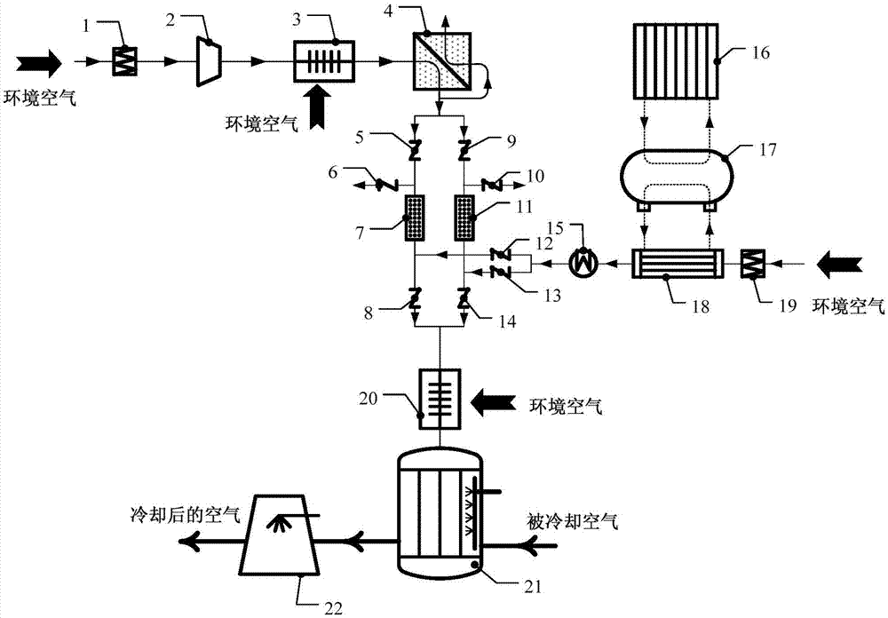
[0037] see figure 1 , a cooling device for dehumidified air in the present invention, comprising an air dehumidification device with a moisture absorber, the air outlet of the air dehumidification device is connected with a cooling device; the air dehumidification device is also connected with a After that, the adsorber regeneration device that regenerates the moisture adsorber, after the ambient air passes through the air dehumidification device to remove the contained moisture, the cooling device lowers the temperature of the air and adjusts it to a suitable humidity, and then passes through the required space to achieve Air conditioning purposes.

[0038] The air dehumidification device includes a supercharger 2, a membrane dehumidification assembly 4 and a moisture adsorber connected in sequence; wherein the supercharger 2 is an oil-free supercharger, and its structure is screw type, scroll type, piston type, Slide vane, Roots or centrifugal. A first filter 1 for removin...

Embodiment 2

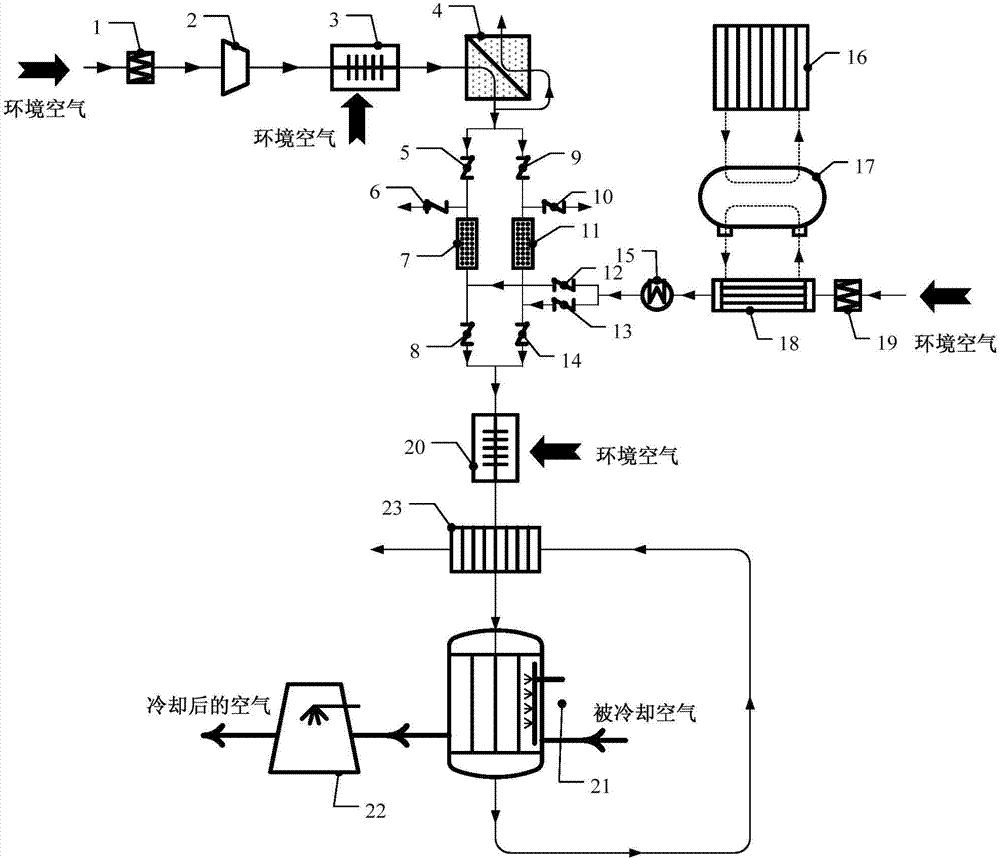
[0043] see figure 2 , considering that the temperature of the gas flowing out from the cold side channel of the indirect evaporative cooler 21 is still relatively low, therefore, in this embodiment, a subcooler 23 is arranged between the third heat exchanger 20 and the indirect evaporative cooler 21, and the indirect evaporative cooler The outlet of the cold side channel of 21 is connected with the inlet of the hot side channel of the subcooler 23, and the outlet of the hot side channel of the subcooler 23 is communicated with the external environment; the outlet of the hot side channel of the third heat exchanger 20 is connected with the outlet of the subcooler 23 The inlet of the cold side channel is connected, and the outlet of the cold side channel of the subcooler 23 is connected with the inlet of the hot side channel of the indirect evaporative cooler 21 . The gas is passed into the inlet of the hot side channel of the subcooler 23 to further cool the gas flowing out of...


PUM


Abstract

The invention discloses a dehumidification air cooling apparatus and a cooling method. The dehumidification air cooling apparatus comprises an air dehumidification device provided with a moisture adsorber, wherein an air outlet of the air dehumidification device is connected with a cooling device, and the air dehumidification device is further connected with an adsorber regeneration device used for regenerating the moisture adsorber after excessive moisture is adsorbed by the moisture adsorber. The water vapor content of air in an external environment is reduced through the air dehumidification device, and then the air exchanges heat with cooled air flowing through a cold-side channel of an indirect evaporative cooler to achieve the purpose of dehumidifying and cooling the cooled air, and meanwhile, the cooled air enters a direct evaporative cooler to further achieve the required temperature and humidity. According to the invention, the techniques of membrane separation and adsorption are combined together, and an evaporative cooling technique is adopted to cool and absorb heat, so that a system can work in a high-humidity environment, the integrated energy efficiency ratio is high and the maintenance workload is small.

Description

technical field [0001] The invention belongs to the technical field of air conditioning and membrane separation, and relates to an air cooling device, in particular to a dehumidifying air cooling device and a cooling method. Background technique [0002] The cooling and adjustment of air is a necessary means to improve people's living environment or ensure the normal operation of equipment. Usually, forced ventilation or appropriate refrigeration technology can be used to achieve it. However, the former is mainly determined by the external environment and cannot be fundamentally solved. The latter is the main method used in air conditioning at present. The common ones are the mechanical compression refrigeration method using freon working fluid, the absorption or ejection refrigeration method driven by heat energy, but these methods all have the disadvantages of large energy consumption or difficult maintenance. shortcoming. [0003] With my country's emphasis on low-carbon...

Claims


Application Information

Patent Timeline
Patent Type & Authority Applications(China)
IPC IPC(8): F24F3/14
Inventor 董继先严彦王博
Owner SHAANXI UNIV OF SCI & TECH
Why Eureka
Try Eureka