Check patentability & draft patents in minutes with Patsnap Eureka AI!

Electromagnetic tracking system and method based on electric control rotary magnetic field

A technology of rotating magnetic field and tracking system, applied in the field of electromagnetic tracking, can solve problems such as poor search flexibility and poor system real-time performance, and achieve the effects of improving real-time performance, avoiding positioning errors, and improving positioning speed

Inactive Publication Date: 2014-02-12
FUDAN UNIV
View PDF3 Cites 21 Cited by
  • Summary
  • Abstract
  • Description
  • Claims
  • Application Information

AI Technical Summary

Problems solved by technology

[0004] This method of realizing the electromagnetic tracking of the rotating magnetic field through mechanical scanning can accurately locate, but its positioning speed is limited by the rotation speed of the solenoid driven by the stepping motor, and the real-time performance of the system is poor; and the mechanical scanning can only be performed when the stepping motor is limited. in the rotation plane, the search flexibility is poor

Method used


Image

  • Electromagnetic tracking system and method based on electric control rotary magnetic field
  • Electromagnetic tracking system and method based on electric control rotary magnetic field
  • Electromagnetic tracking system and method based on electric control rotary magnetic field

Examples


Embodiment Construction

[0061] The composition and working process of the system will be described below in conjunction with specific embodiments and with reference to the accompanying drawings. The coordinate system definition involved in this specific embodiment is the same as Table 1, as Figure 6 Shown; The definition of the latitude and longitude angle involved is the same as the content of the invention.

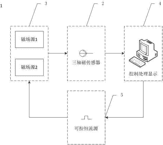
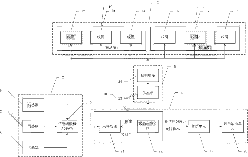
[0062] This specific embodiment designs figure 1The electromagnetic tracking system 1 shown includes four parts: a three-axis magnetic sensor device 2 , a magnetic field source device 3 , a control processing display device 4 , and a controllable constant current source device 5 . The sensor device 2 is attached to the tracking target. The magnetic field source device 3 includes two magnetic field sources 10 and 11 (corresponding to the magnetic field source 1 and the magnetic field source 2 described in the summary of the invention and the claims), each of which is wound on a magnetic cor...


PUM


Abstract

The invention belongs to the technical field of electromagnetic tracking, and particularly relates to an electromagnetic tracking system and method based on an electric control rotary magnetic field. The electromagnetic tracking system consists of a triaxial magnetic sensor device, a magnetic field source device, a controllable constant current source device and a control processing display device. The electromagnetic tracking method comprises the following steps: exciting three orthogonal coils by the controllable constant current source device to form a magnetic field source; scanning with synthetic magnetic induction intensity maximum value generated by the magnetic field source according to a search strategy by the control processing display device controlling each excitation current intensity output by the constant current source device, and finally, appointing the synthetic magnetic induction intensity maximum value to the position of the triaxial magnetic sensor device; and calculating the six-degree-of-freedom position and posture of the sensor according to two groups of angle information obtained by scanning the two magnetic field sources and finally appointing to the triaxial magnetic sensor and according to distance information between central points of the two magnetic field sources. The electromagnetic tracking system and method do not depend on some supposed magnetic field model or iterated algorithm, are high in stability and low in computational complexity, can be applied to navigation of minimally invasive surgeries, and also can be applied to the fields of virtual (enhanced) reality, three-dimensional ultrasonic imaging and the like.

Description

technical field [0001] The invention belongs to the technical field of electromagnetic tracking, in particular to an electromagnetic tracking system and method for realizing magnetic field rotation by controlling the excitation current of a magnetic field source coil. Background technique [0002] Electromagnetic tracking is a method of tracking the spatial position and attitude of the target by using the magnetic field coupling relationship between the magnetic field source and the magnetic sensor. It has broad application prospects in minimally invasive surgical navigation and has become a research hotspot in the field of target tracking. Compared with other tracking methods, electromagnetic tracking has the advantages of no damage, no radiation, no occlusion problems, easy operation, accurate positioning, and complete positioning information (can realize three-dimensional six-degree-of-freedom positioning: three-degree-of-freedom position and three-degree-of-freedom direc...

Claims


Application Information

Patent Timeline
IPC IPC(8): G01C21/00
CPCA61B17/00234A61B90/10
Inventor 邬小玫沙敏王一枫丁宁金炼
Owner FUDAN UNIV
Features
  • R&D
  • Intellectual Property
  • Life Sciences
  • Materials
  • Tech Scout
  • Unparalleled Data Quality
  • Higher Quality Content
  • 60% Fewer Hallucinations
Learn More