Ultrasonic transducer sound field measuring method based on dynamic photoelastic method

A technology of dynamic photoelasticity and ultrasonic transducers, applied in the direction of measuring ultrasonic/sonic/infrasonic waves, measuring devices, instruments, etc., can solve problems such as inability to propagate transverse waves, cumbersome operation, and difficulty in ensuring consistency

Inactive Publication Date: 2014-02-12
INST OF ACOUSTICS CHINESE ACAD OF SCI
View PDF3 Cites 11 Cited by
  • Summary
  • Abstract
  • Description
  • Claims
  • Application Information

AI Technical Summary

Problems solved by technology

Since water can only propagate longitudinal waves, not transverse waves, the water immersion method can only measure the sound field of longitudinal wave transducers
Moreover, the sound velocity and acoustic impedance of water are very different from the metal materials commonly used in industry. The sound field measured by the water immersion method cannot reflect the real sound field in the metal, and its application is limited.
[0004] The test block method needs to prepare a series of semicircular test blocks with different diameters, the uniformity of the test blocks is difficult to guarantee, and the different diffusion angles of each test block must be scanned once, which is more cumbersome to operate
In particular, the shear wave transducer needs to be pasted on the surface of the test block. Every time a measurement point is changed, the receiving transducer must be pasted again. The scanning process is more cumbersome and the consistency is difficult to guarantee.
[0005] Therefore, the sound field characteristics measured by the traditional ultrasonic transducer sound field test method are affected by the characteristics of the receiving transducer and the receiving circuit, and are not the actual sound field

Method used


Image

  • Ultrasonic transducer sound field measuring method based on dynamic photoelastic method
  • Ultrasonic transducer sound field measuring method based on dynamic photoelastic method
  • Ultrasonic transducer sound field measuring method based on dynamic photoelastic method

Examples


Embodiment Construction

[0022] The technical solutions of the present invention will be described in further detail below with reference to the accompanying drawings and embodiments.

[0023] The method for measuring the ultrasonic transducer of the present invention is to utilize the dynamic photoelasticity method to collect the transient sound field image and the steady-state sound field image of the stress size and distribution of the radiation sound field, and through the processing of the transient sound field image and the steady-state sound field image, Finally, the accurate characteristics of the sound field of the ultrasonic transducer are obtained.

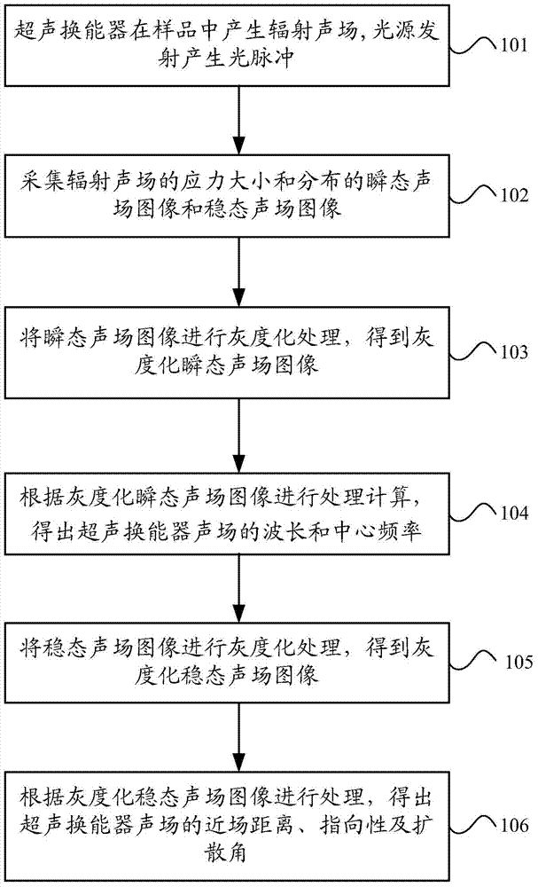
[0024] figure 1 It is a flowchart of Embodiment 1 of the method for measuring the sound field of an ultrasonic transducer of the present invention. As shown in the figure, the method includes the following steps:

[0025] In step 101, the ultrasonic transducer generates a radiation sound field in the sample, and the light source emits light pu...


PUM


Abstract

The invention relates to an ultrasonic transducer sound field measuring method based on a dynamic photoelastic method. The measuring method includes the following steps that an ultrasonic transducer generates a radiation sound field in a sample, and a light source emits to generate light pulses; stress intensity, a distributed transient sound field image and a distributed steady sound field image of the radiation sound field are collected; graying processing is performed on the transient sound field image to obtain a grayed transient sound field image; the grayed transient sound field image is processed through calculation, and the wave length and center frequency of the ultrasonic transducer sound field are obtained; graying processing is performed on the steady sound field image to obtain a grayed steady sound field image; the grayed steady sound field image is processed, and the near field distance, the directivity and the spread angle of the ultrasonic transducer sound field are obtained. By the adoption of the dynamic photoelastic method, the ultrasonic transducer sound field measuring method can rapidly and accurately obtain the information of the ultrasonic transducer sound field by using processing of the transient sound field image and the steady sound field image.

Description

technical field [0001] The invention relates to a method for measuring the sound field of an ultrasonic transducer, in particular to a method for measuring the sound field of an ultrasonic transducer based on a dynamic photoelastic method. Background technique [0002] An ultrasonic transducer is a device that converts other forms of energy into sound energy. Among the ultrasonic generation methods, piezoelectric transducers are the most widely used. The test of ultrasonic transducer sound field plays a fundamental role in ultrasonic detection. There are two traditional methods for testing the sound field of ultrasonic transducers: one is the water immersion method; the other is the test block method. [0003] The water immersion method generally fixes a small steel ball with a diameter of 1mm in water, changes the inclination angle of the ultrasonic transducer and the distance from the steel ball, and gradually measures the ultrasonic transducer’s vibration amplitude by m...

Claims


Application Information

Patent Timeline
Patent Type & Authority Applications(China)
IPC IPC(8): G01H9/00
Inventor 安志武廉国选毛捷王小民金士杰陈秋颖冷涛张逸君宋波
Owner INST OF ACOUSTICS CHINESE ACAD OF SCI
Why Eureka
Try Eureka