Surface foreign material detecting system and control method thereof

A technology of foreign matter inspection and control method, which is applied in the direction of optical testing flaws/defects, instruments, measuring devices, etc., which can solve the problems of large-scale inspection of difficult-to-inspect objects and prolonged inspection time, and achieve the effect of saving inspection time and cost

Inactive Publication Date: 2014-02-12
SAMSUNG ELECTRO MECHANICS CO LTD
View PDF7 Cites 4 Cited by
  • Summary
  • Abstract
  • Description
  • Claims
  • Application Information

AI Technical Summary

Problems solved by technology

[0007] However, such a surface inspection method using bright field illumination or dark field illumination is only partially performed on the surface of the object to be inspected. Therefore, it is not only difficult to inspect a large area of ​​the object to be inspected, but also to prevent The detected scattered light is converted into each pulse signal for detection, which has the disadvantage of prolonging the inspection time
[0008] In addition, in the conventional surface inspection method, since the illumination light is irradiated on the surface of the object to be inspected at an incident angle, on a surface with a high reflectance such as a metal surface, the surface itself is strongly generated not from foreign matter but from the surface itself. Scattering, there is a disadvantage that it is difficult to apply the conventional surface inspection method

Method used


Image

  • Surface foreign material detecting system and control method thereof
  • Surface foreign material detecting system and control method thereof
  • Surface foreign material detecting system and control method thereof

Examples


Embodiment Construction

[0044] Through the following detailed description of the drawings and preferred embodiments, the purpose, specific advantages and new features of the present invention will become clearer. In this specification, it must be noted that when reference numerals are attached to the constituent elements of each drawing, the same constituent elements are limited to the same constituent elements, and the same reference numerals are attached as much as possible even if they are shown in another drawing. In addition, although terms such as first and second can be used to describe various constituent elements, the constituent elements are not limited by the terms. The terms are only used for the purpose of distinguishing one component from another. In the description of the present invention, if it is judged that the specific description of the known technology involved may make the gist of the present invention unclear, the detailed description will be omitted.

[0045] Hereinafter, a pre...


PUM


Abstract

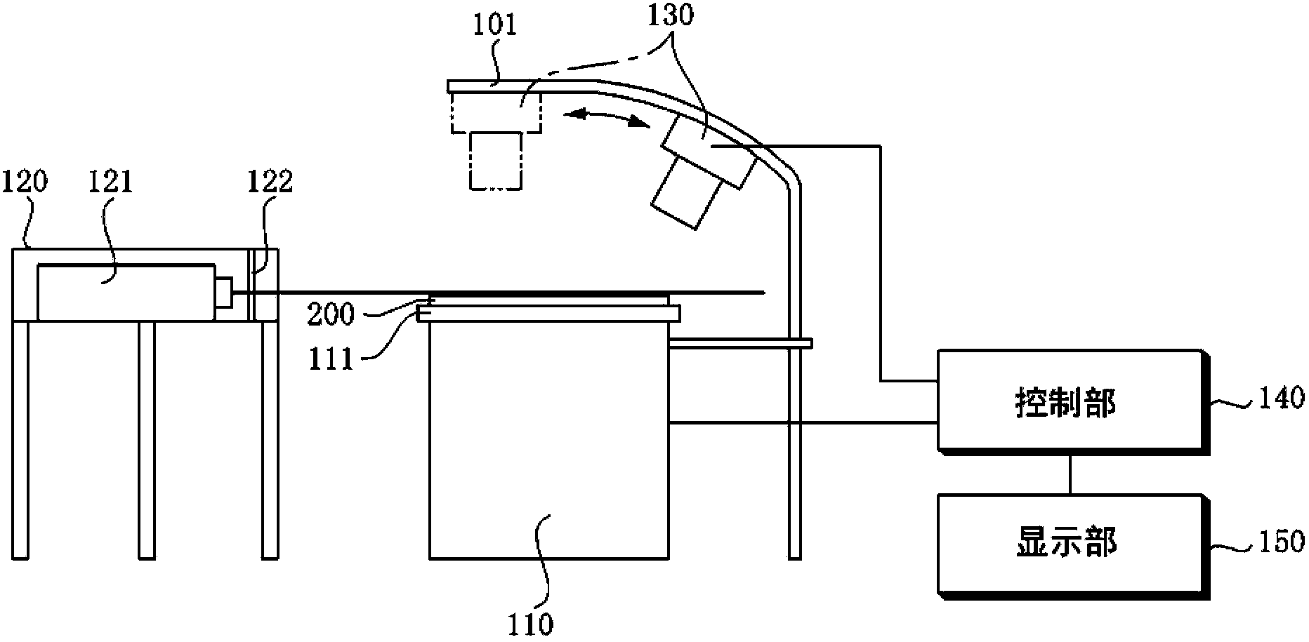
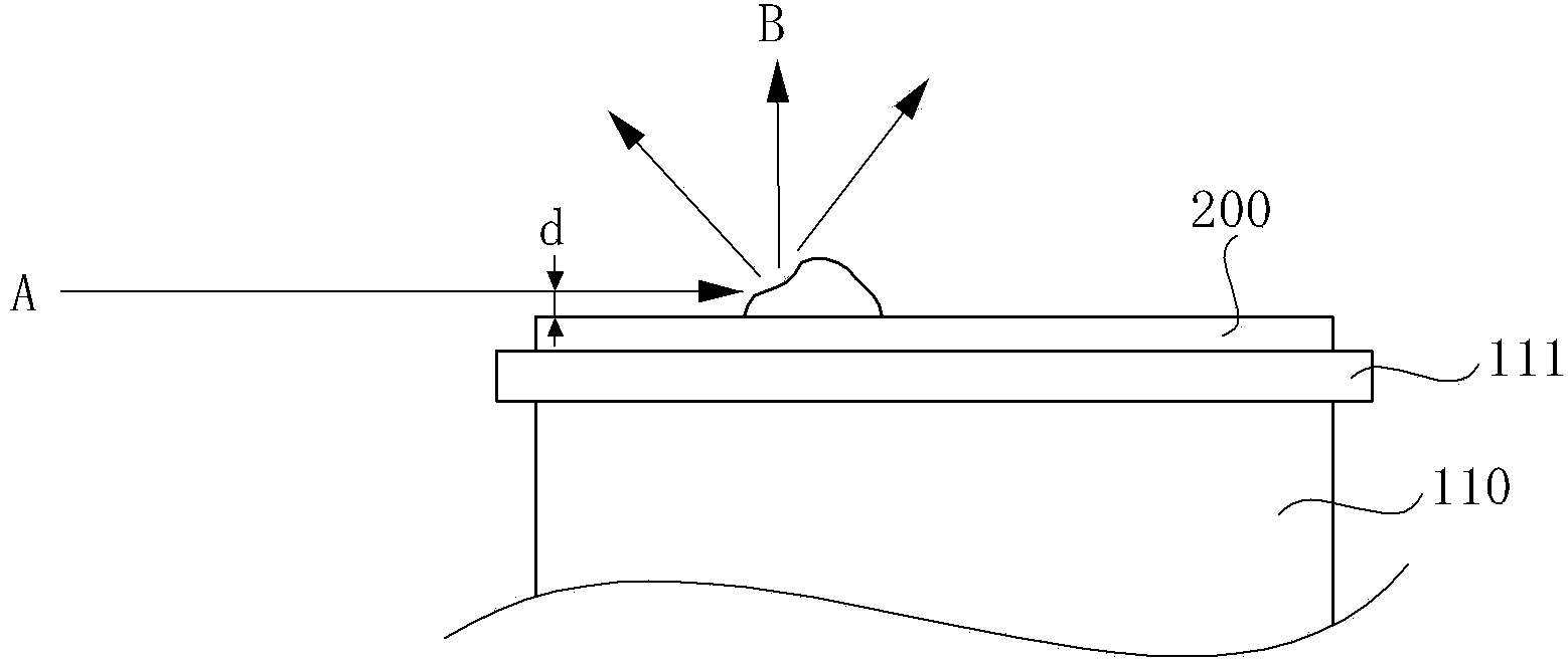
The invention relates to a surface foreign material detecting system and a control method thereof. The surface foreign material detecting system comprises a platform part, a light source irradiating part, a supporting bench, a shooting part, a control part, and a display part. A detected object is disposed on an upper part of the platform part, and the platform part can be used to adjust the height of the upper part. The light source irradiating part can be separated from the platform part, can be used to irradiate the light for the checking parallel to the surface of the detected object according to the checking condition. The shooting part is disposed on the above mentioned supporting bench, can be used to receive the light scattered from the surface of the detected object, and shoot the image information of the foreign material information of the detected object. The control part is connected with the platform part, the light source irradiating part, and the shooting part, and is used to receive the image information, and can be used to detect the surface foreign material information. The display part can be used to display the surface foreign material information.

Description

Technical field [0001] The invention relates to a surface foreign matter inspection system and a control method thereof. Background technique [0002] The conventional surface defect inspection device refers to the following device, that is, as described in Korean Patent Application No. 2006-0080306 (filed on August 24, 2006), including the test object to be measured and the lighting device The light source unit, the inspection camera for acquiring the image of the test object, etc., use image processing technology to determine whether there is a defect on the surface of the test object from the image acquired by such a test camera. [0003] The types of methods for inspecting surface defects using the light source unit of such a surface defect inspection apparatus can be roughly classified into a bright field illumination method and a dark field illumination method (Dark Field Illumination). [0004] First of all, the bright-field illumination method is in a structure composed of l...

Claims


Application Information

Patent Timeline
Patent Type & Authority Applications(China)
IPC IPC(8): G01N21/88
CPCG01B11/303G01N21/8806G01N21/94G01N21/95G01N21/95684
Inventor 闵泰泓韩基镐
Owner SAMSUNG ELECTRO MECHANICS CO LTD
Why Eureka
Try Eureka