Reactive voltage control method and system for grid-connected photovoltaic power station

A voltage control method and photovoltaic power station technology, applied in photovoltaic power generation, AC network voltage adjustment, reactive power compensation, etc., can solve problems such as weak voltage regulation capability, increased voltage at grid-connected points, and grid loss

Active Publication Date: 2014-02-12
CHONGQING UNIV
View PDF1 Cites 25 Cited by
  • Summary
  • Abstract
  • Description
  • Claims
  • Application Information

AI Technical Summary

Problems solved by technology

Among them, the constant power factor cosφ control, when the photovoltaic active output is very small, in order to maintain the power factor unchanged, the photovoltaic system still needs to generate a certain amount of reactive power, which increases the loss of the grid; the cosφ(P) control based on the photovoltaic active output, according to the photovoltaic The power factor value of the active output of the system is changed from C1 to C2 to overcome the shortcomings of cosφ control, but the premise of this control strategy is to assume that the grid-connected point voltage increases with the increase of photovoltaic active output. When the p

Method used


Image

  • Reactive voltage control method and system for grid-connected photovoltaic power station
  • Reactive voltage control method and system for grid-connected photovoltaic power station
  • Reactive voltage control method and system for grid-connected photovoltaic power station

Examples


Embodiment Construction

[0073] The preferred embodiments of the present invention will be described in detail below in conjunction with the accompanying drawings; it should be understood that the preferred embodiments are only for illustrating the present invention, rather than limiting the protection scope of the present invention.

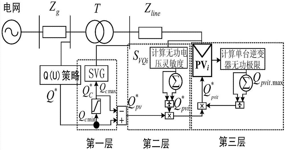
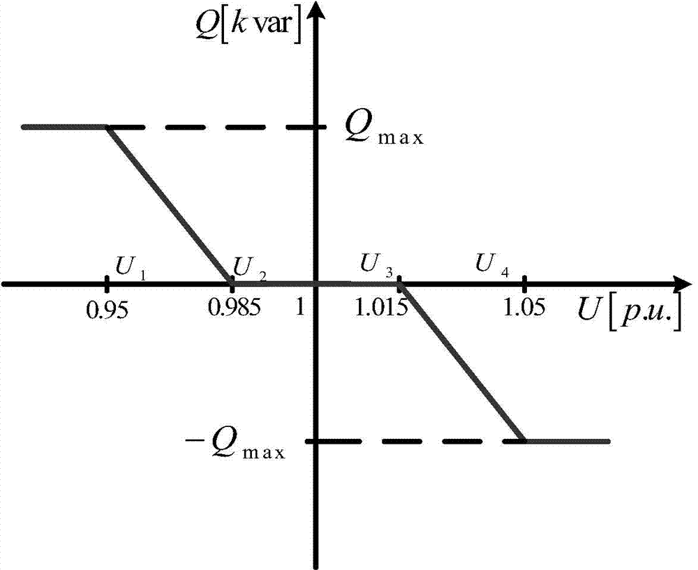
[0074] figure 1 It is a schematic diagram of voltage coordinated control of a photovoltaic power station provided by an embodiment of the present invention. In the figure, T represents a step-up transformer of a photovoltaic power station, and Z line Indicates the sum of the impedance of the collector line and transformer inside the photovoltaic power station, Z g represents the line impedance, figure 2 The schematic diagram of the drooping curve of the Q(U) control method provided by the embodiment of the present invention is shown in the figure: the reactive voltage control method of the grid-connected photovoltaic power station provided by the present invention inc...


PUM


Abstract

The invention discloses a reactive voltage control method and system for a grid-connected photovoltaic power station. A three-layer reactive power control strategy is adopted to coordinate the reactive output between a reactive compensation device and a photovoltaic power generation unit and between inverters of a single photovoltaic power generation unit. Under the control strategy, the reactive voltage support is provided for the power grid; the photovoltaic power station can effectively regulate the power grid voltage; the active loss and the reactive loss of the power grid are minimal on the premise of keeping the power grid voltage within the required range. A photovoltaic array power reduction running strategy is further combined, the stable operation of the power grid is ensured on the premise of maintaining a certain reactive output capacity of the photovoltaic power station. The reactive voltage control method and the system solve the problem that the voltage at the grid-connected point is out of limit, which is caused by the fact that the large-scale photovoltaic power station is connected to the power grid, increase the permeability of the photovoltaic current in the power grid, and improve the stable running performance of the power grid voltage.

Description

technical field [0001] The invention relates to the field of photovoltaic power station control, in particular to a method and system for controlling reactive power and voltage of a grid-connected photovoltaic power station. Background technique [0002] In recent years, with the continuous reduction of photovoltaic system costs and the maturity of photovoltaic grid-connected technology, large-scale photovoltaic power generation has become more and more favored by the international community. Large-scale photovoltaic power plants are generally built in remote areas with abundant solar energy resources. Compared with small and medium-sized photovoltaic systems, solar energy can be used more intensively, and parallel inverters can be controlled and managed. However, as the proportion of photovoltaic power generation in the power grid continues to increase, photovoltaic power needs to be transmitted to the load center over long distances, and the photovoltaic system has an adve...

Claims


Application Information

Patent Timeline
IPC IPC(8): H02J3/16H02J3/38
CPCY02E40/34Y02E10/563Y02E10/56Y02E40/30
Inventor 周林晁阳廖波郭珂刘强杨明张密郑光辉
Owner CHONGQING UNIV
Why Eureka
Try Eureka