
Machining method and machining device of jet nozzle

A processing method and a technology of a processing device, which are applied in the processing of nozzles and processing devices of nozzles, can solve problems such as difficulties in inner cone surfaces, achieve good chip removal effects, reduce wear, and reduce chip accumulation.

Active Publication Date: 2014-02-19
CHINA HANGFA SOUTH IND CO LTD
View PDF6 Cites 19 Cited by
  • Summary
  • Abstract
  • Description
  • Claims
  • Application Information

AI Technical Summary

Problems solved by technology

[0005] The purpose of the present invention is to provide a processing method for a spout and a processing device for a spout, so as to solve the problem of difficulty in processing the inner cone of the spout in the prior art

Method used


Image

  • Machining method and machining device of jet nozzle
  • Machining method and machining device of jet nozzle
  • Machining method and machining device of jet nozzle

Examples


Embodiment Construction

[0028] It should be noted that, in the case of no conflict, the embodiments in the present application and the features in the embodiments can be combined with each other. The present invention will be described in detail below with reference to the accompanying drawings and examples.

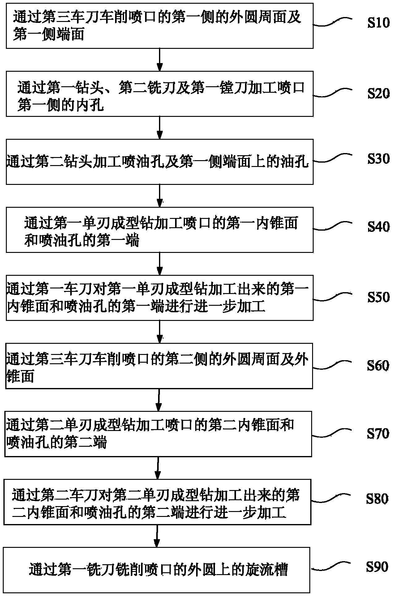
[0029] Such as figure 1 and figure 2 As shown, the spout processing method of the present embodiment comprises the following steps:

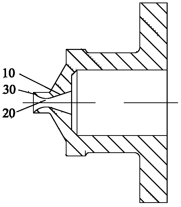
[0030] Step S40: Machining the first inner tapered surface 10 of the nozzle and the first end of the fuel injection hole 20 through the first single-edged form drill;

[0031] Step S70: processing the second inner tapered surface 30 of the nozzle and the second end of the fuel injection hole 20 through the second single-edged form drill;

[0032] Among them, such as Figure 3 to Figure 5 As shown, both the first single-edged shaped drill and the second single-edged shaped drill include a first handle 110 and a first cutter head 120, the first cutter head 120...


PUM


Abstract

The invention provides a machining method and a machining device of a jet nozzle. The machining method of the jet nozzle comprises the following steps that S40, the first end of a first inner conical surface (10) and the first end of an oil jet hole (20) of the jet nozzle are machined through a first single-blade forming drill; S70, the second end of a second inner conical surface (30) and the second end of the oil jet hole (20) of the jet nozzle are machined through a second single-blade forming drill; the first single-blade forming drill and the second single-blade forming drill respectively comprise a first cutter handle (110) and a first cutter head (120), each first cutter head (120) comprises a first conical section (121), each first conical section (121) is gradually contacted and extends outwards, a first cutting surface (1211) is formed on each first conical section (121) and provided with a fist scrap discharging portion, and one of two edges of each first cutting surface (1211) forms a cutting blade. According to the technical scheme, the machining method and the machining device effectively solve the problem that the inner conical surfaces of the jet nozzle are difficult to machine in the prior art.

Description

technical field [0001] The invention relates to the technical field of mechanical processing, in particular to a method for processing a spout and a device for processing a spout. Background technique [0002] For the processing of small high-precision micro-nozzle parts, major domestic manufacturers are located in Xi'an, Beijing, Shanghai, Zhuzhou and Guizhou. When processing the inner cone surface of the nozzle, it is mainly processed by forming and buried drilling, and after processing, polishing or abrasive flow is used to meet the requirements of the profile size and surface roughness. The cone angle of the cutting edge of the forming buried drill is the same as that of the processing surface. When processing, the cutting edge is full-loaded and the wear is relatively large. In addition, it is difficult for the tool to remove chips, and it is easy to produce chipping, resulting in poor surface quality of parts. Polishing is manual polishing, generally using a cork sti...

Claims


Application Information

Patent Timeline
Patent Type & Authority Applications(China)
IPC IPC(8): B23P15/00B23B51/00B23B27/00B23C5/02
CPCB23B27/00B23B51/00B23C5/02B23P13/02
Inventor 赵强徐舟傅名伟李剑飞贺灿刘博逵张永辉
Owner CHINA HANGFA SOUTH IND CO LTD
Learn More