Screw-type nail extractor specifically for railway signal

A technology for railway signal and nail puller, which is applied to nail pullers, manufacturing tools and other directions, can solve the problems of bulky, inconvenient and unsafe nail pullers, and achieve the effects of low production cost, simple structure and lightening of load.

Inactive Publication Date: 2014-02-19
SICHUAN MINGHENG TECH CO LTD
View PDF8 Cites 4 Cited by
  • Summary
  • Abstract
  • Description
  • Claims
  • Application Information

AI Technical Summary

Problems solved by technology

[0013] The purpose of the present invention is to provide a special rotary nail puller for railway signals, which solves the problems of bulky, inconvenient operation and unsafety of the existing railway signal nail pullers

Method used


Image

  • Screw-type nail extractor specifically for railway signal
  • Screw-type nail extractor specifically for railway signal

Examples


Embodiment

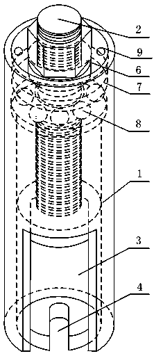
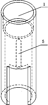
[0033] Such as figure 1 and figure 2 As shown, the special-purpose rotary nail puller for railway signals includes a support sleeve 1 and a puller rod accommodated inside the support sleeve 1. The puller rod includes a screw rod 2. The side of the screw rod 2 is provided with threads. Nail chamber 3, a rotary disk that is threadedly connected to the outer side of the upper end of the screw rod 2 and movably connected to the inner side of the upper end of the support sleeve 1. The screw rod 2 and the staple chamber 3 are of an integrated structure, and the outer side of the staple chamber 3 is movably connected to the inner side of the support sleeve 1 , In this example, the side of the screw 2 is set as a trapezoidal thread.

[0034] In order not to damage the conductive wire connected to the plug during the operation and to easily withdraw after the plug is pulled out, the staple chamber 3 is set as a hollow cylindrical structure, and the side is provided with an opening, w...


PUM


Abstract

The invention discloses a screw-type nail extractor specifically for railway signal, which solves the problems of heavy weight, inconvenient operation and unsafety of current railway signal nail extractors. The screw-type nail extractor specifically for railway signal comprises a support sleeve, a pulling bar is accommodated in the support sleeve, the pulling bar comprises a screw, a thread is provided at the side surface of the screw, a nail clamping chamber arranged at the bottom of the screw, a rotary disk is connected to the thread outside the upper end of the screw and connected to the inner side of the upper end of the support sleeve in a movable mode, the screw and the nail clamping chamber are in an integrated structure, and the outer part of the nail clamping chamber is connected to the inner side of the support sleeve in the movable mode. The screw-type nail extractor has an all-in-one structure, and has the advantages of simple structure, free maintenance, light weight and portability, the screw-type nail extractor has small volume for adapting the entire work environment, and is suitable for large scale popularization and usage.

Description

technical field [0001] The invention relates to a nail puller, in particular to a special rotary nail puller for railway signals. Background technique [0002] In the railway signal equipment, some information needs to be transmitted with the rail as the carrier, but the rail is not a continuous conductor, and each section of the rail or between the rail and the trackside equipment is connected by various connecting wires (hereinafter referred to as the wire) , the way that the conductor wire is connected to the rail is to drill a hole on the rail, and drive the conductor wire end into the rail hole after plugging the nails. And the routine maintenance work of railway signal equipment often needs to change conductor wire, or needs the plug pin of conductor wire to be pulled out from rail when changing rail. [0003] For a long time, signal workers have used iron punches and hand hammers to punch out the plug nails from the reverse side of the plug nails to remove the condu...

Claims


Application Information

Patent Timeline
Patent Type & Authority Applications(China)
IPC IPC(8): B25C11/00
Inventor 朱葆春
Owner SICHUAN MINGHENG TECH CO LTD
Why Eureka
Try Eureka