Placing boom control method, placing boom control device, concrete pump truck and material distributing machine

A technology of control device and control method, which is applied in the directions of transportation and packaging, processing of building materials, load suspension components, etc., to achieve the effects of simplifying control, reducing operation difficulty, improving movement accuracy and flexibility

Active Publication Date: 2014-02-19
SANY AUTOMOBILE MFG CO LTD
View PDF5 Cites 11 Cited by
  • Summary
  • Abstract
  • Description
  • Claims
  • Application Information

AI Technical Summary

Problems solved by technology

[0003] In view of this, the present invention proposes a boom control method and device as well as a concrete pump truck and a distributing machine to solve the problems of the accuracy of the movement direction of the boom end and reduce the difficulty of operation by the operator

Method used


Image

  • Placing boom control method, placing boom control device, concrete pump truck and material distributing machine
  • Placing boom control method, placing boom control device, concrete pump truck and material distributing machine
  • Placing boom control method, placing boom control device, concrete pump truck and material distributing machine

Examples


Embodiment Construction

[0026] It should be noted that, in the case of no conflict, the embodiments of the present invention and the features in the embodiments can be combined with each other. The present invention will be described in detail below with reference to the accompanying drawings and examples.

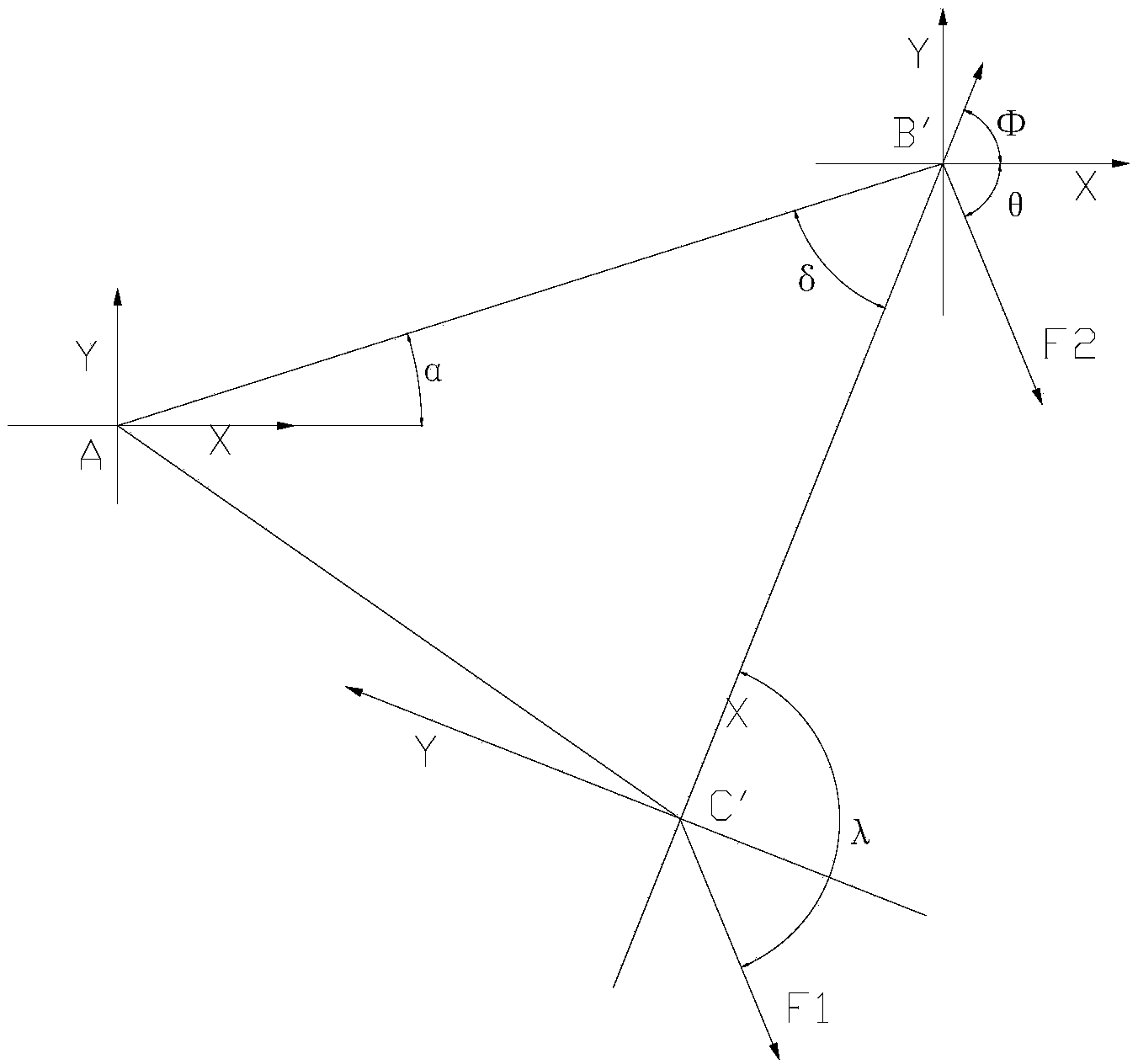
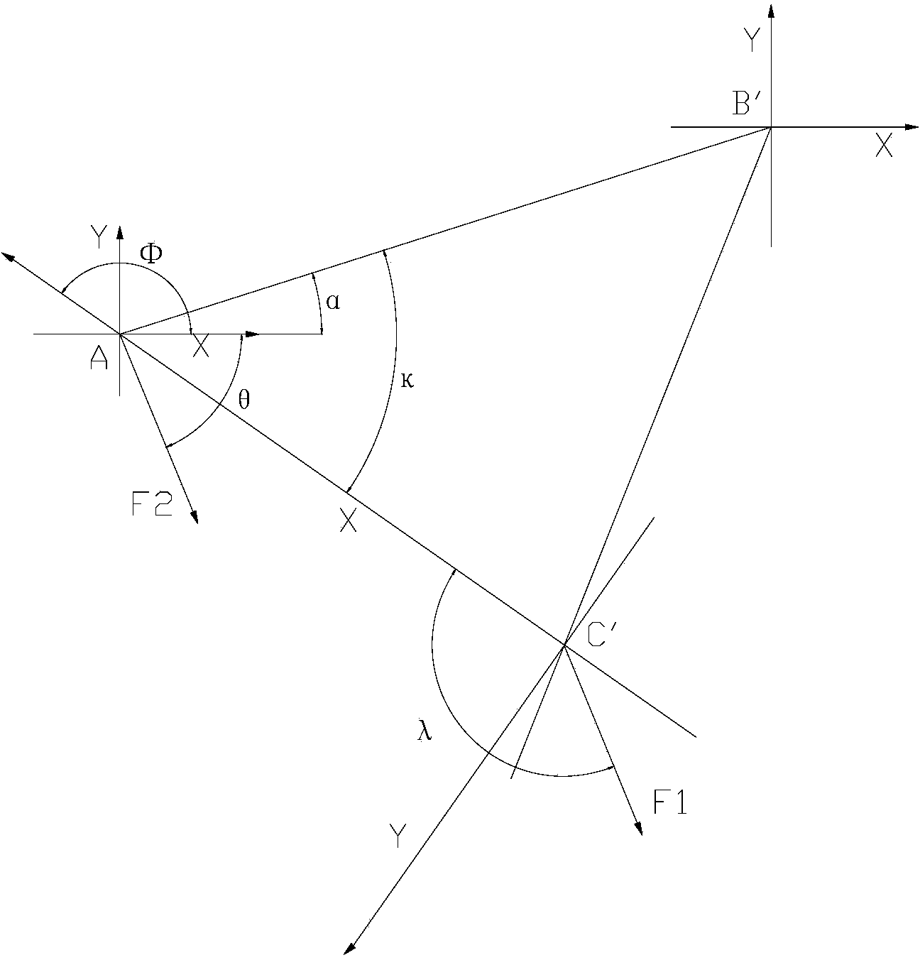
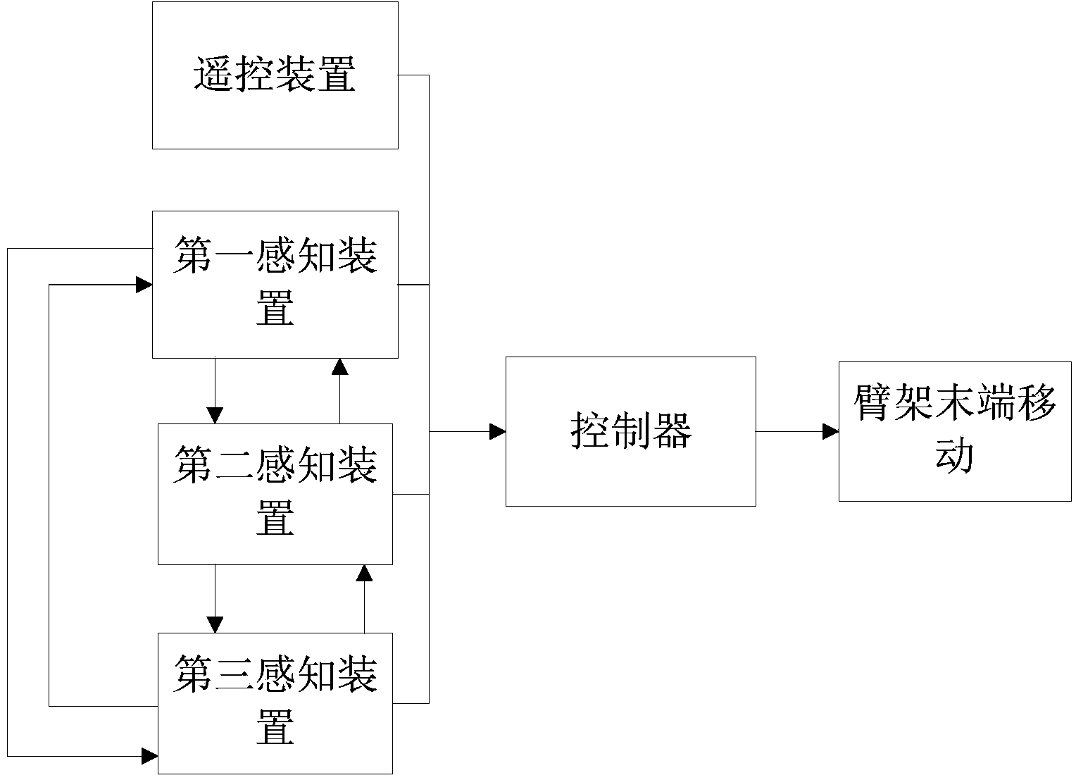
[0027] Combine below figure 1 and figure 2 , the preferred embodiment of the present invention will be further described in detail. The boom control method of this preferred embodiment includes acquiring the swing direction F1 of the operating handle of the remote control device, and controlling the moving direction F2 of the end of the boom to be parallel to the swing direction F1 of the operating handle of the remote control device. When the operating handle of the remote control device swings 360 degrees, the moving direction of the boom end on the horizontal plane is parallel to the projection direction of the swinging direction F1 of the operating handle of the remote control device on the...


PUM


Abstract

The invention discloses a placing boom control method. The placing boom control method comprises the steps that a two-dimensional absolute coordinate system is established on the horizontal plane; a two-dimensional dynamic coordinate system is established on the horizontal plane, wherein the connection line between the original point of the two-dimensional absolute coordinate system and the original point of the two-dimensional dynamic coordinate system is an axis of the two-dimensional dynamic coordinate system, the original point of the two-dimensional absolute coordinate system is located on the rotating central point of a placing boom or the tail end point of the placing boom, and the original point of the two-dimensional dynamic coordinate system is located on a remote control device; the angles formed between the swinging direction of an operating hand shank of the remote control device and the coordinate axes of the two-dimensional dynamic coordinate system are obtained; the angle that the two-dimensional dynamic coordinate system rotates relative to the two-dimensional absolute coordinate system is obtained; through coordinate system conversion computation, the angles formed between the swinging direction of the operating hand shank of the remote control device and the coordinate axes of the two-dimensional absolute coordinate system are obtained to control the tail end of the placing loom to move. The invention further discloses a placing boom control device and a concrete pump truck. According to the placing boom control method, the placing boom control device, the concrete pump truck and a material distributing machine, the degree of intellectualization is high, operation difficulty of an operator is reduced, and moving accuracy and flexibility performance of the tail end of the placing loom are improved.

Description

technical field [0001] The invention relates to the field of engineering machinery, in particular to a boom control method and device, a concrete pump truck and a distributing machine. Background technique [0002] The concrete pump truck and the placing machine mainly transport the concrete to the point to be poured through the boom system, and the control of the moving direction of the boom end is completely controlled by the operator's experience. At present, the boom system of the concrete pump truck and the distribution machine is composed of multi-joint mechanical arms, and the remote control device is equipped with multiple operating handles. If the boom system is composed of 5 joint arms, the remote control device has 5 operating handles and the operating handle for boom rotation, each operating handle controls the movement of each section of the boom, and the operation of each section of the boom is not related to each other, and the moving direction of the end of t...

Claims


Application Information

Patent Timeline
Patent Type & Authority Applications(China)
IPC IPC(8): E04G21/04
CPCE04G21/0463B66C13/40E04G21/0436
Inventor 谭凌群蒲东亮武利冲
Owner SANY AUTOMOBILE MFG CO LTD
Why Eureka
Try Eureka