A jet-suction anti-tempering anti-explosion cutting torch

An anti-backfire, injection-suction technology, applied in the direction of gas fuel burners, combustion methods, combustion types, etc., can solve the problems of reducing the flow rate of the mixture, limiting the flow rate of the mixture, and decreasing the speed, so as to prevent the backflow of the mixture, The effect of improving safety

Active Publication Date: 2015-11-18
NINGBO LONGXING WELDING CUTTING TECH STOCK
View PDF7 Cites 0 Cited by
  • Summary
  • Abstract
  • Description
  • Claims
  • Application Information

AI Technical Summary

Problems solved by technology

This cutting torch is based on the ordinary jet-suction cutting torch, and a Venturi tube is added at the junction of the jet-suction tube and the mixing tube. Using the characteristics of the Venturi, the preheated oxygen is compressed and raised to subsonic speed, and the preheated oxygen When entering the mixing tube, the gas is sucked away for mixing. Since the flow rate of the preheated oxygen is increased to subsonic speed, the flow rate of the mixed gas has been significantly increased compared with the original one, and the phenomenon of backflow of the mixed gas has been curbed to a certain extent. The area where the mixed gas is formed in the torch is relatively large. In practical applications, it will cause stagnation and buffering of the mixed gas, which will reduce the velocity of the initial mixed gas with subsonic velocity, and the mixed gas must pass through the straight mixing tube to reach the torch. In this way, when the mixed gas is formed and passes through the mixing tube, the airflow collides with the airflow or the airflow collides with the inner wall of the mixing tube, which further reduces the flow rate of the mixed gas. Therefore, the mixed gas flow rate of the cutting torch is not only unstable but also Absolute advantage, still has the possibility of flashback explosion
[0005] In addition, the Chinese Utility Model Patent Publication No. 2662082 also discloses a dual-purpose welding and cutting torch of isobaric injecting gasoline and gas. It can reach the cutting nozzle quickly, but the flow rate of the mixed fuel is limited, there is no slight advantage, and the mixing area is also large. In practical applications, the flame is still easy to enter the mixing area and the gas pipe

Method used


Image

  • A jet-suction anti-tempering anti-explosion cutting torch
  • A jet-suction anti-tempering anti-explosion cutting torch
  • A jet-suction anti-tempering anti-explosion cutting torch

Examples


Embodiment 1

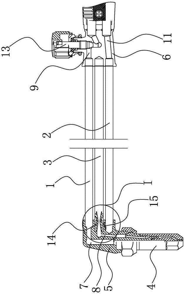
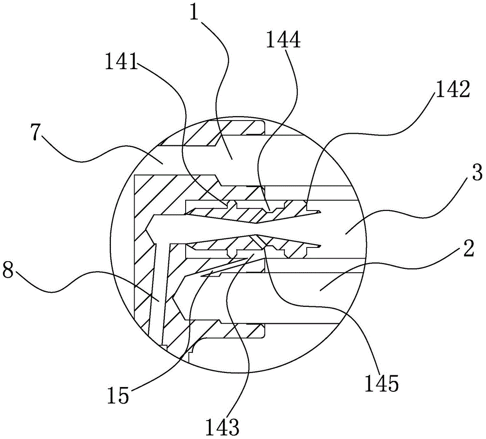
[0027] Embodiment one: if figure 1 , figure 2 and image 3As shown, a jet-suction anti-tempering and anti-explosion cutting torch mainly includes cutting oxygen pipe 1, gas pipe 2, preheating oxygen pipe 3, cutting nozzle 4, cutting nozzle joint 5, middle body 6, and cutting nozzle 4 is installed on On the cutting nozzle joint 5, there are cutting oxygen passages 7 and mixed gas passages 8 inside the cutting nozzle 4 and the cutting nozzle joint 5, and they are connected correspondingly. Road 9 is the oxygen main pipe at the rear of the cutting torch, which is divided into two parts, not shown in the figure) and gas gas channel 11, and a preheating oxygen regulating valve is installed on the middle body 6 (the structure is the same as that of the cutting oxygen regulating valve 13, as shown in Fig. not shown in ) and the cutting oxygen regulating valve 13, the two ends of the cutting oxygen pipe 1 are respectively connected with the cutting oxygen passage 7 on the cutting n...

Embodiment 2

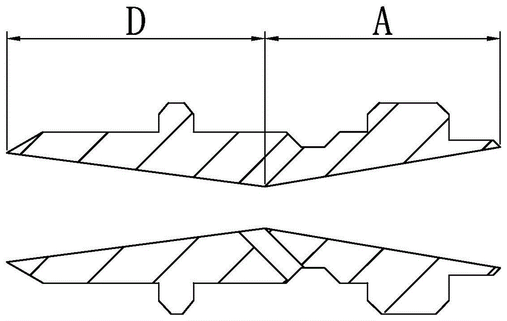
[0034] Embodiment two: if Figure 4 As shown, the overall structure is the same as that of Embodiment 1, the difference is that the inner wall of the nozzle 14 channel is arc-shaped along the axial direction, and along the forward direction of the air flow, a compression section A, an expansion section B and a stable transition section C are formed in sequence, and the compression section A The length is 4mm, the diameter of the inlet end of the compression section A is larger than the diameter of the outlet end of the compression section A, the length of the expansion section B is 3mm, the diameter of the inlet and outlet ends of the expansion section B is the same as the diameter of the outlet end of the compression section A, and the diameter of the expansion section B The diameter of the middle part is slightly smaller than the diameter of the inlet and outlet ends of the expansion section B, and the length of the stable transition section C is 3mm. The diameter of the inl...


PUM


Abstract

The invention relates to an injection type tempering-resistant anti-detonation cutting torch and belongs to the field of welding and cutting devices. According to an existing injection type cutting torch, the tempering phenomenon always occurs and potential safety hazards exist. According to the injection type tempering-resistant anti-detonation cutting torch, a nozzle is installed on the end portion of a cutting tip connector in a preheating oxygen tube, a nozzle channel is formed through connection of two sections of conic channels, the two ends of the nozzle channel are large in diameter and the middle of the nozzle channel is small in diameter, fluid in the preheating oxygen tube passes through the nozzle channel and enters the cutting tip connector, a gas hole communicated with the nozzle channel is formed in the outer circumference of the nozzle, a fuel tube is located on the end portion of the cutting tip connector and provided with a connecting tube, and the fuel tube is connected with the gas hole through the connecting tube. According to the structure of the injection type tempering-resistant anti-detonation cutting torch, the flow speed of mixed gas flow is increased to supersonic speed, the gas flow rapidly enters the cutting tip connector and reaches a cutting tip, so that backflow of the mixed gas flow is effectively prevented, and therefore the injection type tempering-resistant anti-detonation cutting torch has the advantages that safety is improved, the structure is simple, the overall weight is not increased, and the anti-detonation performance is achieved.

Description

technical field [0001] The invention belongs to the field of welding and cutting equipment, in particular to a jet-suction anti-tempering and anti-explosion cutting torch. Background technique [0002] During welding and cutting operations, ordinary jet-suction cutting torches often produce tempering phenomena, which cause the gas in the mixing tube to be ignited and cause a tube explosion, or spread to the gas bottle and cause an explosion, which may damage the equipment in the slightest or endanger life in severe cases. The main reason for the tempering phenomenon is that most of the high-pressure oxygen is used for combustion, and the pressure of the mixed gas is low, and the flow rate is slow and unstable, so that the molten metal close to the cutting nozzle cannot be blown away in time, thus increasing the resistance around the cutting nozzle. Large, the mixed gas in the cutting torch is difficult to flow out, the pressure rises, and part of the mixed gas is pressed int...

Claims


Application Information

Patent Timeline
Patent Type & Authority Patents(China)
IPC IPC(8): F23D14/42F23D14/82
Inventor 俞安康张建达
Owner NINGBO LONGXING WELDING CUTTING TECH STOCK
Why Eureka
Try Eureka