
Heating system for performing seasonal solar energy storage with ground-source heat pump

A ground-source heat pump and heating system technology, applied in heating systems, household heating, household heating, etc., can solve the problems of small contribution of the system and unit, small solar radiation, and inability to monitor soil temperature data in real time , to achieve the effect of feasible technical scheme, economical heating system and improvement of system efficiency

Active Publication Date: 2014-02-19
TIANJIN UNIV
View PDF12 Cites 23 Cited by
  • Summary
  • Abstract
  • Description
  • Claims
  • Application Information

AI Technical Summary

Problems solved by technology

The problem with this device is that it cannot realize the cross-season utilization of solar energy, and it can only be used in the heating season, and the amount of solar radiation that can be utilized in the heating season is small, and the contribution to the improvement of the energy efficiency of the system and the unit is not large
The problem with this device is that there is no ground temperature test system, and the soil temperature data cannot be monitored in real time. In addition, it lacks an automatic control device for the circulating pump, and cannot realize the automatic control of the start and stop of the circulating pump.
The problem with this device is that the coupled utilization of solar energy and ground source heat pumps can only be used in the heating season, and it cannot realize the inter-seasonal energy storage of solar energy.
The problem with this device is that it can only realize the short-term energy storage process of solar energy, and cannot achieve the purpose of solar energy storage across seasons
At the same time, there is no ground temperature testing device in the system, and it is impossible to monitor the temperature data of the soil in real time

Method used


Image

  • Heating system for performing seasonal solar energy storage with ground-source heat pump

Examples


Embodiment Construction

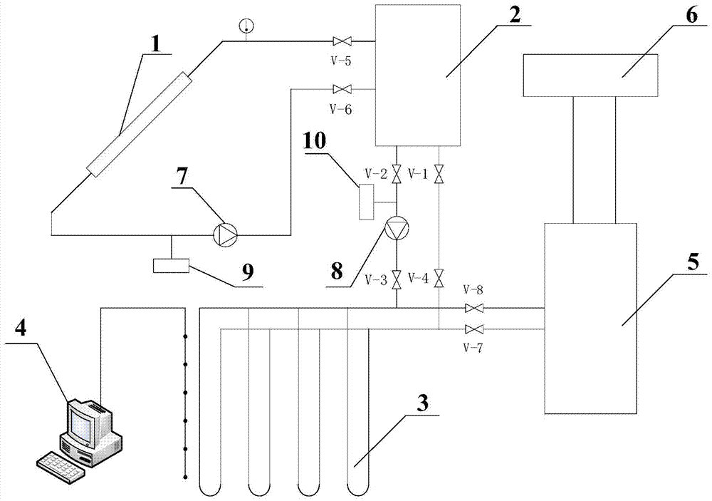
[0023] As shown in the accompanying drawings, a heating system utilizing a soil source heat pump to store solar energy across seasons according to the present invention comprises: (1) a solar heat collector 1; The water outlet of the water tank is connected to the water inlet of the solar collector through the outlet pipeline equipped with the fifth valve V-5, and the water outlet of the solar collector and the water inlet of the hot water tank are installed in sequence according to the direction of water flow. The first automatic controller 9, the first circulation pump 7 and the inlet pipeline of the sixth valve V-6 are connected, and the signal output end of the first automatic controller is connected with the first circulation pump 7 through the first signal control line. (3) ground temperature recording system 4, the signal input end of this ground temperature recording system is connected with the signal output control line of the geotemperature measuring device buried in...


PUM


Abstract

The invention discloses a heating system for performing seasonal solar energy storage with a ground-source heat pump. The heating system comprises a solar thermal collector (1), a thermal collection water tank (2), a ground temperature recording system (3), a plurality of underground buried pipe heat exchangers (4), a soil heat pump unit (5) and a heating user (6), wherein a signal input end of the ground temperature recording system (3) is connected with a signal output control line of a ground temperature measuring device buried underground; the underground buried pipe heat exchangers are buried underground and arranged in parallel connection; a pipeline water inlet of the heating user is communicated with a water supply outlet of the soil heat pump unit through a heating pipeline, and a pipeline water outlet of the heating user is communicated with a water supply and water return port of the soil heat pump unit through a water return pipeline. The heating system has the advantages of being simple in structure, reliable in control and economically feasible. Meanwhile, a large amount of solar energy heat is stored in the thermal storage process, and thus the soil temperature is raised and the system efficiency of the soil source heat pump is improved. The heating system for performing seasonal solar energy storage with the ground-source heat pump is economical and safe.

Description

technical field [0001] The invention relates to a heating system, in particular to a heating system using a soil source heat pump to store solar energy across seasons. Background technique [0002] Ground source heat pump technology is a high-efficiency energy-saving air-conditioning system that utilizes underground shallow geothermal resources. By inputting a small amount of high-grade energy, it realizes the process of transferring low-grade heat energy to high-grade energy, and has a high primary energy utilization rate. Usually the ground source heat pump consumes 1KW of energy, and the user can get more than 4KW of heat or cold, and the extra energy comes from the soil. In addition, the relatively constant temperature of the ground energy makes the operation of the heat pump unit more reliable and stable, ensuring the high efficiency and economy of the system. In winter, the heat in the soil is "taken" out to provide indoor heating; in summer, the heat in the room is t...

Claims


Application Information

Patent Timeline
IPC IPC(8): F24D11/02F24D19/10
CPCY02B10/20Y02B10/70
Inventor 赵靖朱能刘龙
Owner TIANJIN UNIV
Learn More