
Multi-incoming-line standby power supply automatic switching-in method

A backup power supply and automatic input technology, applied in emergency power supply arrangements, electrical components, circuit devices, etc., can solve the problems of difficult and multiple incoming line power supply structure standby automatic switching control, small scope of application, and small number of incoming lines, etc. The effect of automatic power supply recovery, ensuring safe operation and improving power supply reliability

Active Publication Date: 2014-02-19
长园深瑞继保自动化有限公司
View PDF4 Cites 34 Cited by
  • Summary
  • Abstract
  • Description
  • Claims
  • Application Information

AI Technical Summary

Problems solved by technology

[0003] The backup power automatic switch-on device used in the substation in the prior art is difficult to realize the backup automatic switch-on control of the multi-incoming power supply structure. Its structure is simple and the scope of application is small. For the closing of the incoming line, there is no backup power self-injection device that can effectively identify the power source of multiple incoming lines.

Method used


Image

  • Multi-incoming-line standby power supply automatic switching-in method
  • Multi-incoming-line standby power supply automatic switching-in method
  • Multi-incoming-line standby power supply automatic switching-in method

Examples


Embodiment Construction

[0043] The present invention will be further described below in conjunction with the drawings.

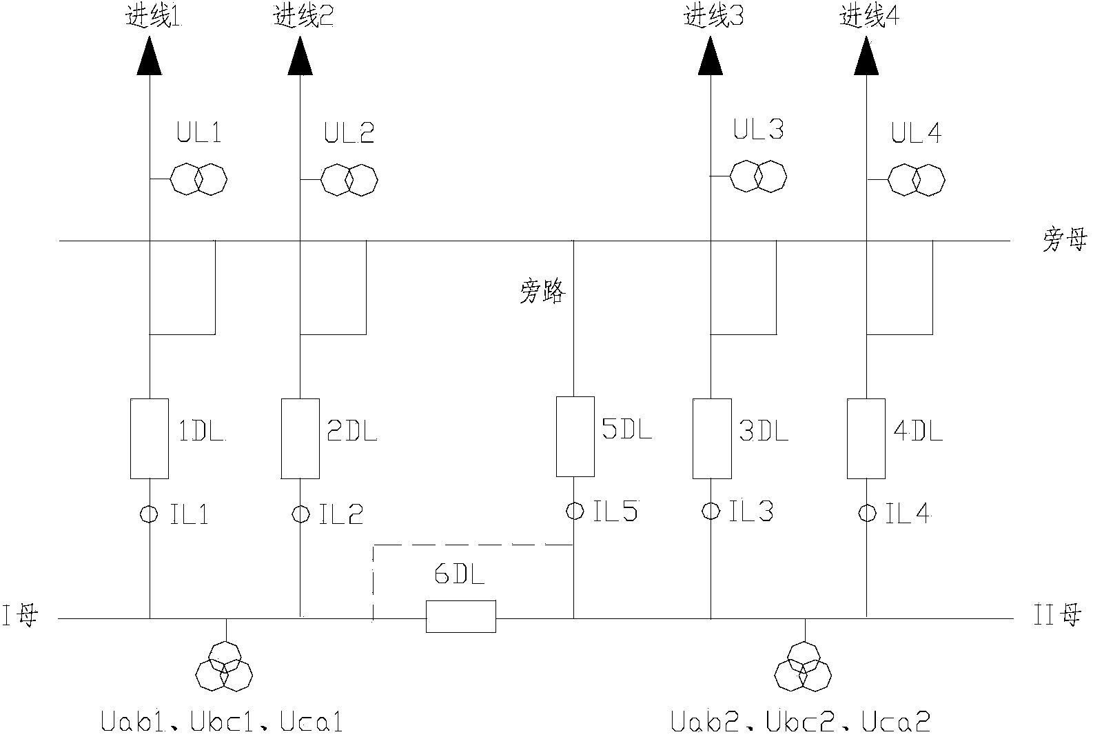
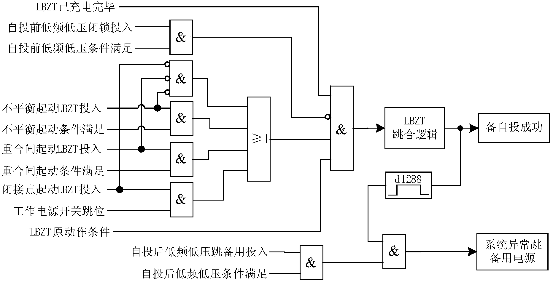
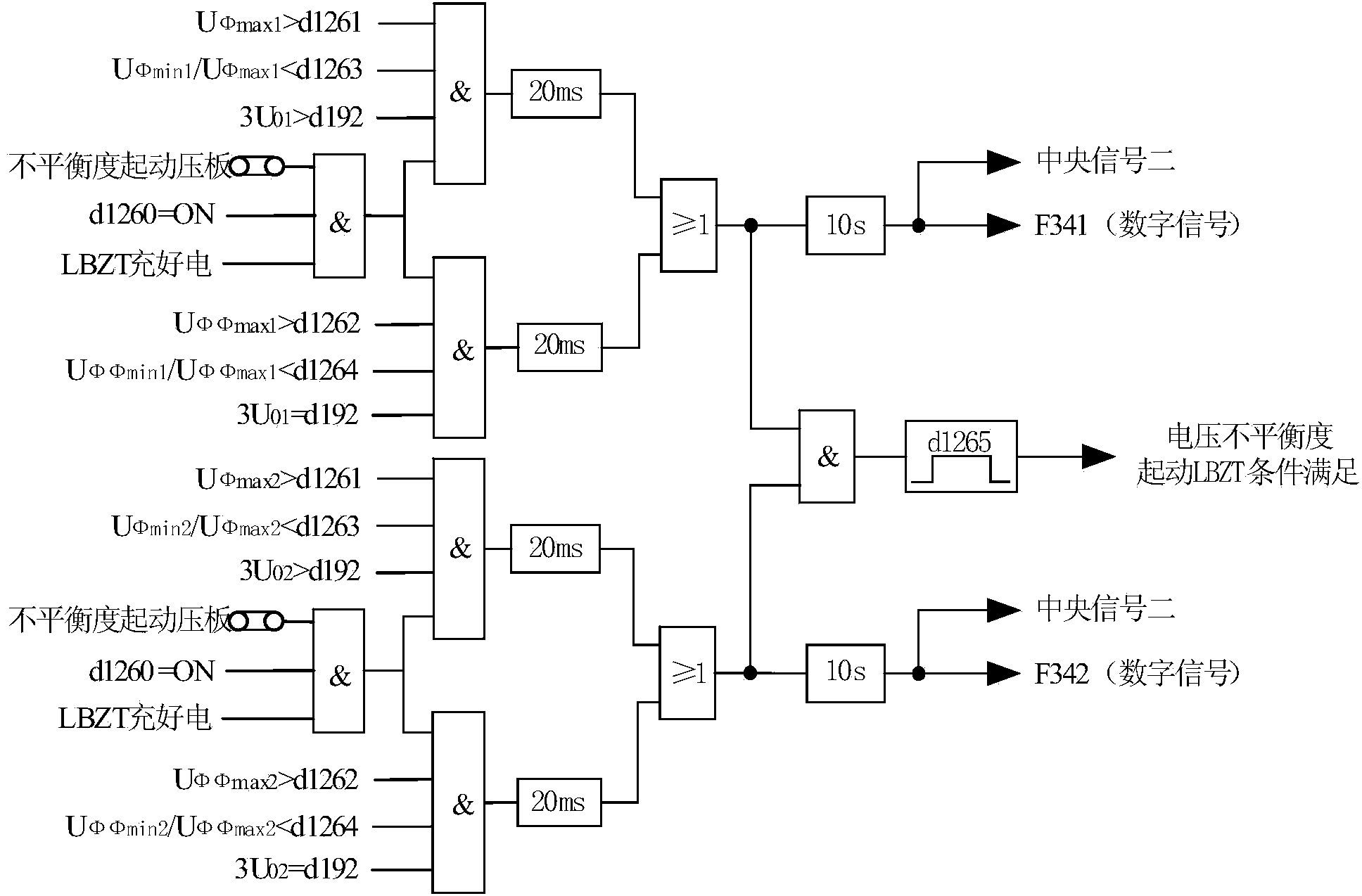
[0044] The multi-incoming standby power supply automatic input method of the present invention is designed for the main wiring of the substation with single bus, single bus with bypass, single bus section and single bus section with bypass, and the designed standby power automatic input device (also The method of standby self-investment (called equipment self-investment device) includes the following contents:

[0045] A. Centrally install automatic input devices on the bus and incoming lines to collect information on the operation of the power supply network such as bus voltage, incoming line voltage, incoming line current, and incoming line and section switch positions;

[0046] B. According to the actual situation of each incoming power source on site, set the incoming power source and action priority setting value, so that the standby automatic switching device can automatically ident...


PUM


Abstract

The invention discloses a method for enabling a standby power supply automatic switching-in device with multiple power supplies and multiple incoming lines of a transformer substation to perform standby power supply automatic switching-in fast, efficiently and accurately. According to the method, the standby power supply automatic switching-in device is arranged on busbars and incoming lines in a centralized mode to collect operation information of a power supply network and determine detailed criteria on the states of all the incoming lines, busbar working power supplies and standby power supply automatic switching-in action logic, wherein the busbars and the incoming lines relate to single busbars, signal busbars with bypasses, single busbar segments and single busbar segments with bypasses. Thus, the standby power supply automatic switching-in device can automatically identify the operation states of all the incoming lines and the sources of power supplies of all the incoming lines of a multi-incoming-line power supply grid, identify standby circuits according to preference constant values, automatically select an action mode and preferably close circuits which have high preference constant value grades, ensure that circuits (such as double-circuit lines) of the same power supply source do not participate in mutual-switching-in, enable two systems to undergo loop closing, greatly improve the power supply reliability of the power supply network, achieve automatic power restoration of the power supply network and ensure safe operation of power systems.

Description

Technical field [0001] The invention relates to a method for automatic input of standby power in a substation, in particular to a method for automatic input of standby power of a substation with multi-incoming line bypass and multi-inlet section with bypass. Background technique [0002] With the rapid development of social economy, the demand for electricity in various industries is increasing, and the requirements of power users for the reliability of power supply of the power grid are getting higher and higher, and there are more and more substations with multi-circuit power supply lines. It has become a consensus in the industry to use automatic standby power input devices suitable for multiple incoming lines to improve the power supply reliability of the power grid. [0003] In the prior art, the automatic switch-in device for standby power used in substations is difficult to realize the automatic switch-in control of the multi-incoming power supply structure. Its structure is...

Claims


Application Information

Patent Timeline
IPC IPC(8): H02J9/06
CPCY02B70/30Y04S20/20
Inventor 许永军徐成斌杨志荣叶玩忠王薛东向莉华
Owner 长园深瑞继保自动化有限公司
Learn More