
A Combined Artificial Middle-section Prosthesis of Femur

A combined, artificial technology, applied in prostheses, femurs, bone implants, etc., can solve problems such as weak pull-out and anti-rotation forces, defects, and prosthesis replacement failures, to improve surgical efficiency and simple operation. , the effect of simple structure

Inactive Publication Date: 2016-01-20
SHANGHAI TENTH PEOPLES HOSPITAL
View PDF6 Cites 0 Cited by
  • Summary
  • Abstract
  • Description
  • Claims
  • Application Information

AI Technical Summary

Problems solved by technology

From the analysis of the cross-section, this straight cylinder can only complete the positioning and adhesion in the X and Y directions, and the interlocking of the distal and proximal ends of the prosthesis does not have a reliable positioning force, and the interlocking screws at the distal and proximal ends of the prosthesis do not. A reliable positioning force, resulting in obvious defects in the interface between the prosthesis stem and the bone cement interface (the femoral end on both sides of the prosthesis), weak pull-out and anti-rotation forces, and easy damage to the prosthesis stem and the inner wall of the medullary cavity. loosening between the prosthetic replacements
To obtain the interlocking force firstly depends on the fixation method of the prosthesis stem and the femoral ends on both sides of the prosthesis. The shape of the contact surface (the direction of the bone cement) cannot be ignored when the bone cement fixation is used to obtain the maximum contact surface. Currently, bone cement Type prosthesis cannot make the bone cement form a reliable X, Y, Z three-way force between the bone marrow cavity and the prosthesis to reflect its strong pull-out resistance and anti-rotation force

Method used


Image

  • A Combined Artificial Middle-section Prosthesis of Femur
  • A Combined Artificial Middle-section Prosthesis of Femur
  • A Combined Artificial Middle-section Prosthesis of Femur

Examples


Embodiment Construction

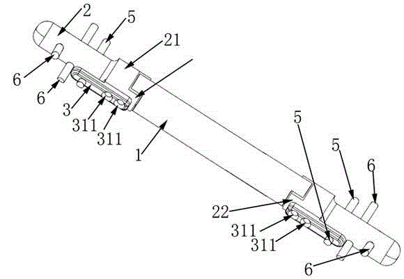
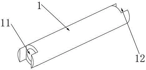
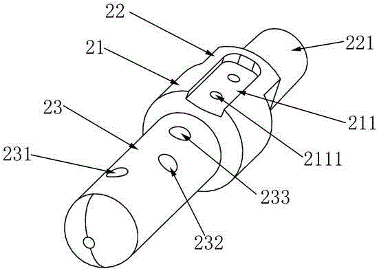
[0028] Below in conjunction with accompanying drawing, the present invention is described in further detail, so that those skilled in the art understand:

[0029] like Figure 1-4 As shown, the labels represent:

[0030] Femoral stem component 1, blind hole 11, straight groove 12, femoral stem component 2, base part 21, opening groove 211, screw hole 2111, boss 22, cylinder 221, handle 23, first through hole 231, The second through hole 232 , the third through hole 233 , the side plate 3 , the base 31 , the screw hole 311 , the plate body 32 , the fourth through hole 321 , the side plate screw 5 , and the handle screw 6 .

[0031] The general inventive concept of the present invention is to increase the side protection plate of the prosthesis on the basis of the existing mid-section femur prosthesis, so as to securely fix the prosthesis handle and the femoral ends on both sides of the prosthesis. The specific technical solution, the combined mid-femoral prosthesis is mainly ...


PUM

PropertyMeasurementUnit
Diameteraaaaaaaaaa
Lengthaaaaaaaaaa
Widthaaaaaaaaaa

Abstract

The invention relates to a combined artificial femoral middle prosthesis which comprises a femoral shaft component, two femoral stem components and side plates, wherein the femoral stem components are assembled at two ends of the femoral shaft component, and the side plates are bolted on the femoral stem components. The femoral stem components are provided with coaxial and cylindrical stems, a first through hole, a second through hole and a third through hole are sequentially formed in each stem from head to root and radially staggered, portions of the side plates extending out of a second end are parallel to the stems, a gap is formed between the portion of each side plate and the corresponding stem, the wall of a human femur can be inserted into the gap, a fourth through hole is formed in each side plate and coaxial with the third through hole in the corresponding stem, and a side plate screw is jointly assembled by the aid of each fourth through hole and the corresponding third through hole. The combined artificial femoral middle prosthesis has the advantages that the prosthesis is reasonable in structural design and has excellent pulling resistance and rotating resistance, preparation and surgical operation are facilitated, the risk of looseness and subsidence of the prosthesis is reduced, and the prosthesis is suitable for reconstruction of femoral middle bone defects.

Description

technical field [0001] The invention discloses an artificial femoral prosthesis for reconstructing bone defects in the middle part of the femur, in particular to a combined artificial femoral middle part prosthesis composed of a femoral stem component, a femoral handle component and a side plate. Background technique [0002] Under normal circumstances, if the bone defect bone in the middle femur is to be implanted with a prosthesis, the bone cement is placed in the smooth bone marrow cavity to obtain a smooth straight cylinder, and it is relied on to adhere to the prosthesis and the inner wall of the bone marrow cavity, or The interlocking of the near and far ends of the prosthesis achieves the purpose of fixation. From the analysis of the cross-section, this straight cylinder can only complete the positioning and adhesion in the X and Y directions, and the interlocking of the distal and proximal ends of the prosthesis does not have a reliable positioning force, and the int...

Claims


Application Information

Patent Timeline
IPC IPC(8): A61F2/32
CPCA61F2/28A61F2002/2825A61F2002/30001
Inventor 张春林曹庆宏赵世昌王晖朱忠胜黄荣根
Owner SHANGHAI TENTH PEOPLES HOSPITAL
Learn More