Telescopic nozzle device for narrow gap welding and adjusting method of telescopic nozzle device

A nozzle device, telescopic adjustment technology, applied in welding equipment, welding accessories, electrode support devices, etc., can solve the problems of nozzle seat and sleeve-shaped nozzle shaking, external air being involved in the nozzle inner cavity, and complex nozzle height adjustment mechanism, etc. , to achieve the effect of simple and compact adjustment mechanism, preventing air from being involved in the inner cavity of the nozzle, and increasing the effective protection range of gas

Active Publication Date: 2014-02-26
JIANGSU UNIV OF SCI & TECH
View PDF6 Cites 14 Cited by
  • Summary
  • Abstract
  • Description
  • Claims
  • Application Information

AI Technical Summary

Problems solved by technology

The disadvantages of this welding gas protection device are: ① the shape of the external sleeve-shaped nozzle is a single cylinder, and the effective protection range for the filling weld inside the narrow gap groove is small; ② the center hole of the nozzle seat of the external sleeve-shaped nozzle There is a certain gap between the conductive rod and the outer wall of the conductive rod passing through the nozzle seat. When the conductive rod rotates or shakes at low speed, it is easy to cause the outside air to be involved in the inner cavity of the nozzle, thereby affecting the welding gas protection effect; ③The height of the external sleeve-shaped nozzle The adjustment mechanism is complex, large in size, and low in adjustment accuracy. The core components of the micro-rack and pinion and the locking handwheel are easy to wear after a period of use, resulting in shaking of the nozzle seat and the sleeve-shaped nozzle.

Method used


Image

  • Telescopic nozzle device for narrow gap welding and adjusting method of telescopic nozzle device
  • Telescopic nozzle device for narrow gap welding and adjusting method of telescopic nozzle device
  • Telescopic nozzle device for narrow gap welding and adjusting method of telescopic nozzle device

Examples


Embodiment 1

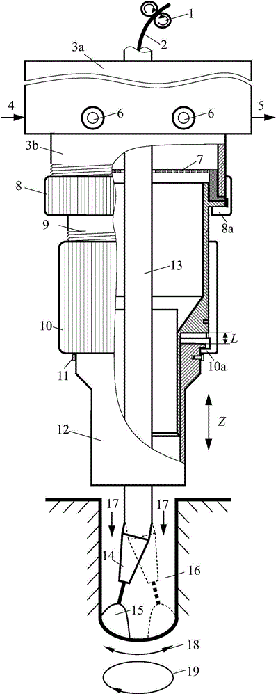
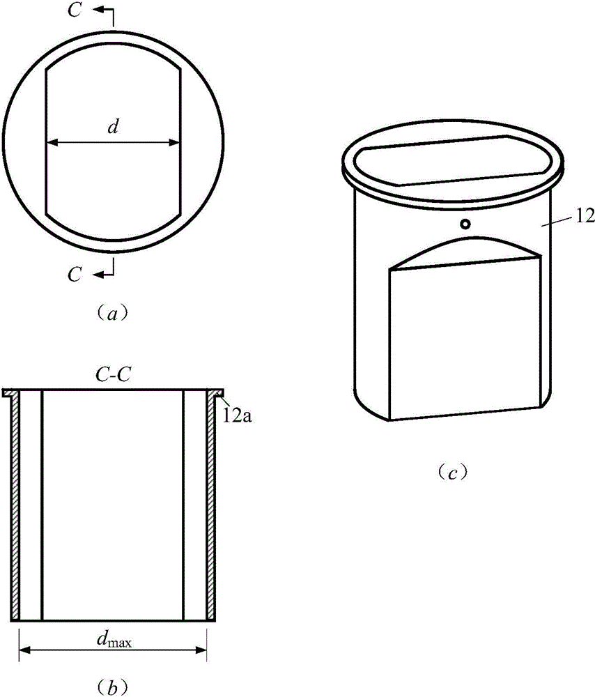
[0042] For the case where the extension length L=0 when the movable nozzle sleeve 12 is moved down, it is suitable for the welding of the initial filling weld when using the retractable nozzle device, such as Figure 6 shown. In actual operation, by turning the telescopic adjustment nut 10, the downward extension length L of the movable nozzle sleeve 12 is reduced to the minimum value (that is, L=0), so that the conductive tip 14 connected to the conductive rod 13 is stretched out and moved The length of the end face of the air outlet of the type nozzle sleeve 12 is L 2 ; Then, through the overall adjustment of the height of the welding torch, the distance from the end face of the gas outlet of the movable nozzle sleeve 12 to the upper surface of the narrow gap welding groove side wall 23 is kept as H 1 (It can be 1~5mm); then according to the given distance L from the contact tip 14 to the bottom of the groove (or the surface of the weld) 1 (Generally selected within the ra...

Embodiment 2

[0045] It is aimed at the welding situation of the general filling weld in the narrow gap groove 16. After each filling weld 24 with an interlayer thickness of t is welded in the narrow gap groove 16, the retractable nozzle device and the conductive rod 13 are raised by a distance t as a whole, and then the telescopic adjusting nut 10 is rotated to move The downward extension length L of the type nozzle sleeve 12 increases the distance t, so that the conductive rod 13 and the conductive tip 14 connected to it gradually retract into the inner cavity of the movable nozzle sleeve 12, and the movable nozzle sleeve 12 The distance from the end face of the air outlet to the upper surface of the narrow gap welding groove side wall 23 is kept at a constant value H 1 , so that when the filling welding operation gradually approaches the upper surface of the groove side wall 23, the best gas shielding effect can still be maintained.

[0046] When the telescopic adjustment limit mark lin...

Embodiment 3

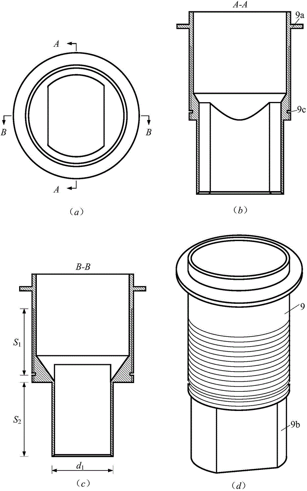
[0048] For the welding situation of the cover weld 25, such as Figure 8 shown. When the cover weld 25 is welded, the depth P of the groove to be welded is already smaller than the interlayer thickness t of the filled weld, and the effect of the groove on the storage of the protective airflow and the constraint on the welding pool is already very small. In this way, on the one hand, it makes The protective effect of the flat nozzles used in Examples 1 and 2 is reduced, and on the other hand, the width of the cover weld 25 is significantly increased. Therefore, it is necessary to replace the nozzle telescopic mechanism composed of the gas calming sleeve 9, the telescopic adjusting nut 10 and the movable nozzle sleeve 12 with an integrated cylindrical sleeve-shaped nozzle 26 with a larger air outlet, so as to provide a suitable surface for the cover weld 25 Provides effective gas protection.

[0049] Summarizing the adjustment process involved in the above embodiments, the adj...


PUM

PropertyMeasurementUnit
depthaaaaaaaaaa

Abstract

The invention discloses a telescopic nozzle device for narrow gap welding and an adjusting method of the telescopic nozzle device. The nozzle device sequentially comprises a nozzle holder, an air sifter cover, a locking nut, a gas calm sleeve, a telescopic adjusting nut and a movable nozzle sleeve from top to bottom, one end of the gas calm sleeve is fixedly connected with the nozzle holder through the locking nut, the other end of the gas calm sleeve is in transmission connection with the telescopic adjusting nut through a thread pair, the movable nozzle sleeve can vertically move along the axial direction of a nozzle under driving of the telescopic adjusting nut, so that the extending length of the movable nozzle sleeve is changed, and the overall axial length of the nozzle is telescopically adjusted. The telescopic nozzle device is compact in structure, convenient to telescopically adjust and wide in effective gas protection range, an inner cavity of the nozzle is fine in gas tightness, and gas protection can be provided for welding seams with different depths in narrow gap grooves.

Description

technical field [0001] The invention belongs to the field of welding technology, and relates to a narrow gap welding nozzle device, and more particularly relates to a retractable nozzle device for narrow gap welding and an adjustment method thereof. Background technique [0002] Narrow-gap gas-shielded arc welding is often used in the welding of high-strength steel with large thick plates. It has good manufacturability, small heat-affected zone of joints, and excellent joint performance. It is a welding technology with high efficiency, high quality and low cost. In narrow-gap gas-shielded arc welding, in order to implement effective and reasonable gas protection for the arc and the welding area in a large-depth narrow-gap groove, existing narrow-gap gas-shielded welding torches are often equipped with two sets of special shielding gas nozzle devices. According to the relative position of the shielding gas nozzle and the narrow-gap welding groove, the nozzle device can genera...

Claims


Application Information

Patent Timeline
Patent Type & Authority Applications(China)
IPC IPC(8): B23K9/28B23K9/26
CPCB23K9/26B23K9/285B23K9/295B23K9/325
Inventor 王加友朱杰马敏刘斌杨峰
Owner JIANGSU UNIV OF SCI & TECH
Why Eureka
Try Eureka