High-strength carbon dioxide corrosion-resisting oil well pipe and manufacturing method thereof
A technology of carbon dioxide and oil well pipes, which is applied in the field of oil well pipes, can solve the problems of low strength level and failure to reach it, and achieve the effect of improving the strength of materials
Active Publication Date: 2014-02-26
BAOSHAN IRON & STEEL CO LTD +1
View PDF12 Cites 8 Cited by
- Summary
- Abstract
- Description
- Claims
- Application Information
AI Technical Summary
Problems solved by technology
[0012] There are also some patents that propose to produce anti-corrosion oil casing with ferrite + pearlite structure without heat treatment such as quenching and tempering. Due to th
Method used
View moreImage
Smart ImageViewing Examples

Examples
 PUM
 Abstract
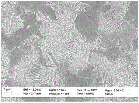
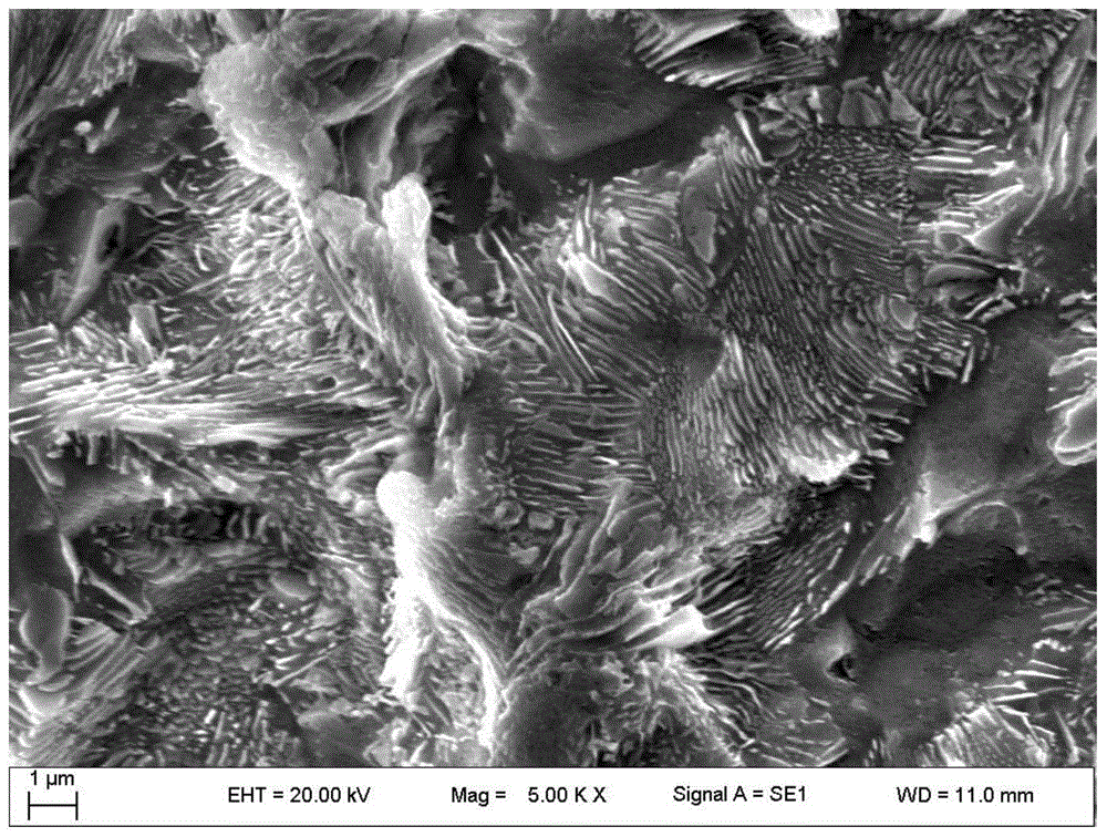
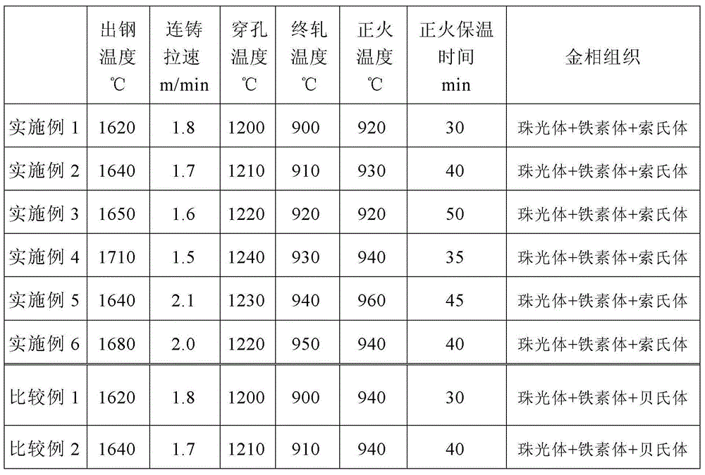
The invention provides a high-strength carbon dioxide corrosion-resisting oil well pipe and a manufacturing method thereof. The manufacturing method comprises the following steps: 1) smelting and casting, wherein the following chemical components are included: 0.30-0.42% of C, 0.10-1.0% of Si, less than or equal to 0.015% of P, less than or equal to 0.005% of S, 0.80-1.5% of Mn, 0.5-1.5% of Cr, 0.21-0.4% of V, 0.01-0.10% of Al, 0.031-0.05% of N, and the balance of Fe and inevitable impurities, by weight percentage, and the ratio of V to N is controlled within the range from 6 to 11; and carrying out smelting, refining outside a furnace and vacuum degassing, and continuously casting into a round billet, wherein the starting steel tapping temperature during steelmaking ranges from 1620 DEG C to 1710 DEG C; 2) evenly heating the round billet in an annular furnace, wherein a perforation temperature ranges from 1200 DEG C to 1240 DEG C, and a final rolling temperature ranges from 900 DEG C to 950 DEG C; and carrying out air cooling on the steel pipe to the room temperature after hot rolling; and 3) normalizing the hot-rolled pipe at a normalization temperature ranging from 920 DEG C to 960 DEG C, preserving heat for 30 to 50 minutes, and carrying out air cooling after discharging out of the furnace. As a result, the mechanical property of the obtained oil well pipe is above 95ksi steel grade; at the normal temperature, the metallographic structure is ferrite+pearlite+sorbite.
Description
technical field [0001] The invention relates to an oil well pipe, in particular to a high strength carbon dioxide corrosion resistant oil well pipe and a manufacturing method thereof. Background technique [0002] CO 2 Corrosion is a common type of corrosion commonly found in the world's petroleum industry, and it is also an extremely prominent problem that plagues the development of my country's oil and gas industry. At present, the main oilfields in China, such as Tarim, Changqing, Sichuan, North China, Shengli, Bonan, and Wenchang, all contain high levels of CO 2 , Cl- and other strong corrosive media, the annual oil well pipe due to CO 2 Accidents caused by corrosion failure have brought economic losses of more than 100 million yuan to the oil field, and have seriously affected the normal and safe production of the oil field. From the perspective of material anti-corrosion, in the environment of high carbon dioxide, chloride ion, salinity and other composite media, th...
Claims
Login to View More Application Information
Patent Timeline
 IPC IPC(8): C22C38/24C21D9/08C21D1/25
Inventor 董晓明张忠铧高展郭毓奕
Owner BAOSHAN IRON & STEEL CO LTD
Features
- Generate Ideas
- Intellectual Property
- Life Sciences
- Materials
- Tech Scout
- Unparalleled Data Quality
- Higher Quality Content
- 60% Fewer Hallucinations
Learn More Browse by: Latest US Patents, China's latest patents, Technical Efficacy Thesaurus, Application Domain, Technology Topic, Popular Technical Reports.
© 2025 PatSnap. All rights reserved.Legal|Privacy policy|Modern Slavery Act Transparency Statement|Sitemap|About US| Contact US: help@patsnap.com