A temperature stress automatic release device for a new rail to be replaced and its application method

A technology of temperature stress and new rails, applied in the field of transportation, can solve the problems of restricting the efficiency of overhaul rail replacement, harsh working environment, and high labor intensity, and achieve the effects of convenient and flexible assembly and disassembly, filling technical gaps, and reducing labor intensity

Active Publication Date: 2015-10-28
TONGJI UNIV
View PDF5 Cites 0 Cited by
  • Summary
  • Abstract
  • Description
  • Claims
  • Application Information

AI Technical Summary

Problems solved by technology

The hotter the weather, the more likely rail expansion will occur. Therefore, the workers work continuously from 7:00 am to 4:00 pm. The labor intensity is high, the working environment is harsh, and the waste of manpower is serious.
In addition, the temperature rise and rail expansion also restrict the efficiency of rail replacement during overhaul. Each skylight time can only change rails for 1.5 kilometers, and the efficiency is low.

Method used


Image

  • A temperature stress automatic release device for a new rail to be replaced and its application method
  • A temperature stress automatic release device for a new rail to be replaced and its application method
  • A temperature stress automatic release device for a new rail to be replaced and its application method

Examples


Embodiment Construction

[0019] The present invention will be further described below in conjunction with the embodiments shown in the accompanying drawings.

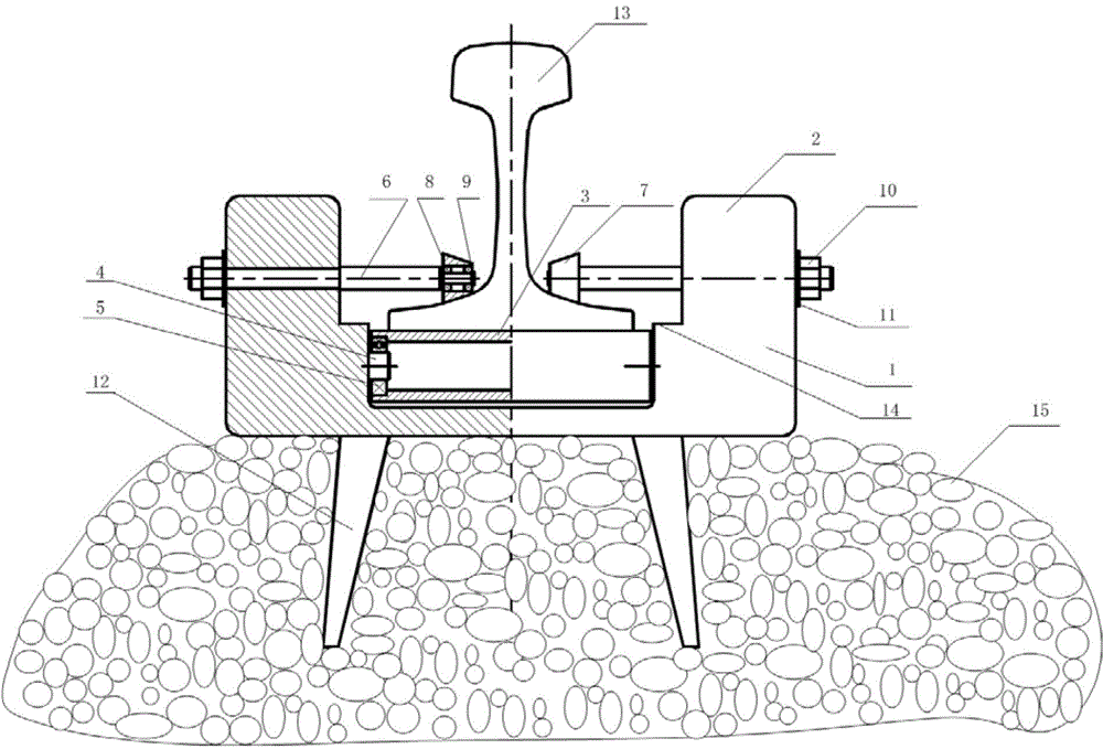
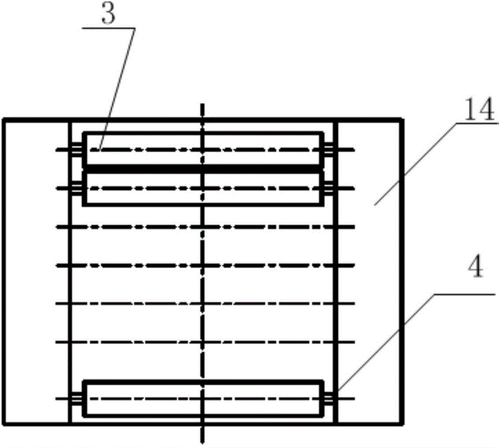
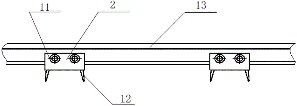
[0020] see Figure 1-3 , the present invention includes: a U-shaped support 1, a U-shaped arm is arranged on the U-shaped support 1, and the U-shaped arm is divided into an upper structure 2 and a lower structure 14, and the lower structure 14 is larger than the upper structure 2 Slightly thicker to form a convex platform; the middle of the U-shaped arm substructure 14 is provided with a cylindrical roller system (see figure 2 ), the cylindrical roller system is composed of several cylindrical rollers 3, several short shafts 4 and several rolling ball bearings 5.

[0021] The short shaft 4 is respectively inlaid on both sides of the lower structure 14 of the U-shaped arm, and the short shaft 4 is connected with the cylindrical roller 3 with a rolling ball bearing 5; the upper limit of the cylindrical roller system is lower than that of the U-...


PUM


Abstract

An automatic temperature stress diffusing device for a standby new rail comprises a U-shaped support base. The U-shaped support base is provided with a U-shaped arm comprising an upper structure and a lower structure. The lower structure is thicker than the upper structure so as to form a boss face. A cylindrical roller system is arranged in the middle of the lower structure of the U-shaped arm, and comprises a plurality of cylindrical rollers, cylindrical shafts and rotary ball bearings. Horizontal limit screws are arranged on two arms of the upper structure of the U-shaped arm respectively. Inserting feet are fixedly connected to the bottom of the U-shaped support base. An application method of the automatic temperature stress diffusing device includes inserting the inserting feet of the U-shaped support base into a railway ballast bed, placing the standby new rail of a jointless rail track on the cylindrical roller system in the U-shaped support base to guarantee even stress of the new rail, and ensuring longitudinal friction force of the steel rail to be reduced during rising of the rail temperature to realize free diffusion of internal temperature stress of the steel rail. The automatic temperature stress diffusing device is simple in structure, and facilitates productivity improvement, worker labor intensity reduction and production safety.

Description

technical field [0001] The invention belongs to the technical field of transportation, and relates to a temperature stress relieving technology for new rails to be replaced, in particular to an automatic temperature stress relieving device for new rails to be replaced for urban rail transit, high-speed railways and ordinary railways, etc. Instructions. Background technique [0002] Usually, before the overhaul of the railway line, 100 meters of steel rails are welded into 1.5 kilometers of new rails to be replaced in the rail welding factory, and then they are consigned to the site of the rail replacement by a rail truck, and placed next to the operating line for a few days or even later. For a long time, if you encounter hot weather, as the rail temperature rises, the rails to be replaced will bulge the runway. In severe cases, the lateral bending of the rails to be replaced will invade the railway boundary, which will cause traffic safety accidents. At present, there is n...

Claims


Application Information

Patent Timeline
Patent Type & Authority Patents(China)
IPC IPC(8): E01B13/02
Inventor 杨新文周宇李新国
Owner TONGJI UNIV
Why Eureka
Try Eureka