Construction device for precast surface and cast-in-place core filler wall

A construction device and prefabricated surface technology, which is applied in the field of building filling walls, can solve the problems of wall flatness not meeting the requirements, stability and rigidity, uneven tension distribution of force cables, etc., and achieve fast and one-way wall formation Improved flexural rigidity and flexural bearing capacity, easy handling and management

Active Publication Date: 2014-02-26
盐城市双新建设投资有限公司
View PDF6 Cites 0 Cited by
  • Summary
  • Abstract
  • Description
  • Claims
  • Application Information

AI Technical Summary

Problems solved by technology

The invention "A self-balancing prefabricated surface and cast-in-place core-filled wall formwork (application number: 201310626576.4)" discloses a forming formwork for prefabricated surfaces and cast-in-place core-filled walls, in which the pressure device is mainly composed of Composed of a force key and a force cable, this pressure device is characterized by a simple structure, light and convenient, and is particularly effective for small-area construction, especially for walls with a small thickness and height. However, when the wall thickness exceeds 100mm or the height exceeds 3m, or when the length of the prefabricated slab is long, the prefabricated pressure, stability and rigidity of the above-mentioned pressure device are somewhat inadequate. The bundling and positioning of prefabricated panels, and when the thickness of the wall increases and the width of the prefabricated panels increases, the length of the force cable used in conjunction with it must also increase accordingly. Too long force cables will cause difficulty in tightening. The tension distribution of the cable itself will be more uneven, and it is easy to break during the process of adding force. On the other hand, when the height of the wall is high, it is necessary to set up multiple force cables in the height direction and increase the corresponding number of force cables on the prefabricated slab. As a result, the amount of construction increases, and the differences between multiple force cables are enlarged, resulting in insufficient stability
In addition, during large-scale construction, due to the lack of a rigid structure to support between adjacent prefabricated panels and pairs of prefabricated panels, the overall rigidity of the construction device is insufficient, and the flatness of the wall cannot meet the requirements

Method used


Image

  • Construction device for precast surface and cast-in-place core filler wall
  • Construction device for precast surface and cast-in-place core filler wall
  • Construction device for precast surface and cast-in-place core filler wall

Examples


Embodiment 1

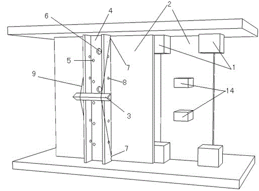
[0049] Prefabricated components: prefabricated panel 2 (length 3200, width 1200, thickness 20) is attached with glass fiber mesh, and the filling core material is gypsum and cement (according to 3:1). The keys 16 (length, width 100, thickness 180) are mass-produced in the factory assembly line using gypsum materials and then transported to the construction site. The six connecting keys 16 and two prefabricated panels 2 are pasted firmly with adhesive to form a cavity mold. Shape positioning key 1 adopts regenerated duroplastic to mass-produce (square section, length 200, width 80, 180 two kinds, thickness 80) in factory assembly line.

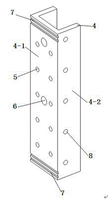
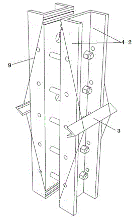
[0050] Construction tools: such as figure 2 with image 3 As shown, the pressure plate 4 is made of plastic steel (groove section: the bottom plate 4-1 is 250 wide, the side plate 4-2 is 150 high, the plate thickness is 10, and the length is 3200). , connecting holes 5 with a spacing of 500, watering holes 6 with a diameter of 50 are provide...

Embodiment 2

[0056] Such as Image 6 As shown, different from Embodiment 1, the prefabricated plate 2 of this example adopts a 10-thick thin plate. Because the plate is thin, for this reason, a drag cable 9 is arranged between the pressure plates 4 at intervals of about 500 cm. Long adjustable structure, the two ends of the cable 9 are passed through the anchor hole 8 of the pressure plate 4 and pinned with wooden bolts, and then the locking keys 14 and the opening keys 13 are alternately arranged between the two strands of the cable 9 to make it shape diamond-shaped, such as Figure 13 with Figure 14 , the locking key 14 adopts a grooved plastic steel clip (length 30, width 30, height 15, wall thickness 5), and the opening key 13 adopts a plastic steel channel plate (length 200, width 50, height 20, wall thickness 5), both ends There are card slots with a width of 10. Two force-applying keys 11 are set between the locking key 14 of the cable 9 and the prefabricated panel 2, and ...

Embodiment 3

[0058] Such as Figure 9 As shown, different from Embodiment 1, the prefabricated plate 2 of this example adopts a 10-thick thin plate. Because the plate is thin, for this reason, a self-balancing stiffener 10 is arranged between the pressure plates 4 at intervals of about 500, and the stiffener 10 I-shaped cross-section plastic steel (length 1200, width 50, height 150, wall thickness 5) is used, and the lower sides of both ends are provided with 200 long serrated grooves (groove depth 10, width 20). Long adjustable structure. The two ends of the stiffener 10 are fixed on the side plate 4-2 of the pressure plate 4, the ring cable 9 is stuck in the sawtooth concave-convex slot 7 at the two ends of the stiffener 10, and the two balance keys 3 are used to pin the cable 9 to the stiffener 10 At one-third and two-thirds of the top surface, make the bending of the cable 9 and the stiffener 10 form a trapezoid, and then move the end of the cable 9 outward to the outer concave-convex...


PUM


Abstract

The invention provides a construction device for a precast surface and cast-in-place core filler wall. The construction device has the advantages that a pressure plate (4) as a pressure applying device has the characteristics of enough rigidity, high strength and the like, and a good pre-pressure effect is achieved by arranging stiffening ribs (10) or stay cords (9) and force applying keys (11) on the pressure plate (4). The entire pressure applying device is simple to install and dismantle, and flexible in configuration, and has a stress self-balancing function. The pressure plate (4), the stiffening ribs (10), the stay cords (9), the force applying keys (11) and the like are massively produced by a factory in a prefabricating manner, the installation is simplified, and the work efficiency is enhanced. As to large-area construction of the filler wall with large thickness and height, the comprehensive economic indexes and the construction duration of the construction device are superior to those of the prior art.

Description

technical field [0001] The invention relates to a building filling wall, in particular to a forming construction device for a prefabricated surface and a cast-in-place core filling wall. Background technique [0002] The building filling wall is the maintenance structure of the building, with a large amount and a wide area. Its sound insulation, heat insulation, strength, fire prevention, moisture resistance, waterproof and other properties directly affect the use performance and safety performance of the building. The invention "A self-balancing prefabricated surface and cast-in-place core-filled wall formwork (application number: 201310626576.4)" discloses a forming formwork for prefabricated surfaces and cast-in-place core-filled walls, in which the pressure device is mainly composed of Composed of a force key and a force cable, this pressure device is characterized by a simple structure, light and convenient, and is particularly effective for small-area construction, esp...

Claims


Application Information

Patent Timeline
Patent Type & Authority Applications(China)
IPC IPC(8): E04G11/08E04B2/86
Inventor 谢孟谢琦
Owner 盐城市双新建设投资有限公司
Why Eureka
Try Eureka