
Magnetic drive submerged pump

A magnetic drive, submerged pump technology, applied in the direction of pumps, pump devices, pump components, etc., can solve the problems of assembly and maintenance difficulties, safety accidents, complex structures, etc., and achieve simple and convenient assembly and maintenance, improved safety, and low cost. Effect

Inactive Publication Date: 2014-02-26
丹东克隆先锋泵业有限公司
View PDF6 Cites 0 Cited by
  • Summary
  • Abstract
  • Description
  • Claims
  • Application Information

AI Technical Summary

Problems solved by technology

[0004] The above-mentioned prior art submerged pump has a complex structure, high cost, and difficult assembly and maintenance.
The medium is prone to leakage, that is, the medium will not only produce a certain amount of leakage at the mechanism seal, but also a large amount of medium leakage will occur when the mechanism sealing device is damaged, and there is a danger of a large amount of medium leakage
When the medium to be transported is toxic, flammable, or explosive, a large amount of leakage of the medium during operation will cause a safety accident

Method used


Image

  • Magnetic drive submerged pump
  • Magnetic drive submerged pump

Examples


Embodiment Construction

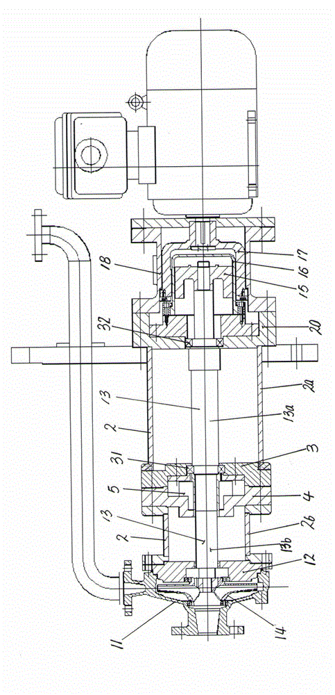
[0011] The magnetic drive submerged pump of the present invention consists of a pump body 11, a pump cover 12, a pump shaft 13, an impeller 14, a shaft frame tube 2, bearing devices 31, 32 installed between the shaft frame tube 2 and the pump shaft 13, and a mechanical seal device. 5. The inner magnetic rotor 15, the spacer sleeve 16, the outer magnetic rotor 17, the connecting frame 18 and the bearing box are composed. The axle frame tube 2 is composed of two sections of tube tubes 2a and 2b butted, and the pump shaft 13 can be composed of two sections of the pump shaft 13a , 13b are formed by the butt joint of the shaft coupling, and the bearing base plate 3 and the sealing gland 4 are fixedly connected between the two ends of the tube tubes 2a and 2b, and the sealed grease-lubricated rolling bearing 31 is arranged between the bearing base plate 3 and the pump shaft 13b. A mechanical seal device 5 is provided on the pump shaft 13b between the bearing seat plate 3 and the seal...


PUM


Abstract

The invention relates to a magnetic drive submerged pump. The magnetic drive submerged pump is characterized by comprising a pump body (11), a pump cover (12), a pump shaft (13), an impeller (14), a shaft bracket cylinder (2), bearing devices (31 and 32) disposed between the shaft bracket cylinder (2) and the pump shaft (13), a mechanical seal (5), an inner magnetic rotor (15), a spacer (16), an outer magnetic rotor (17), and a connecting rack (18). Bearing block discs (3), a seal gland (4), a rolling bearing (31) and a mechanical seal (5) are fixedly connected between end tubes (2a and 2b). The magnetic drive submerged pump is simple in structure, low in manufacturing cost, simple and convenient to assemble and maintain, good in airtightness and safe to use.

Description

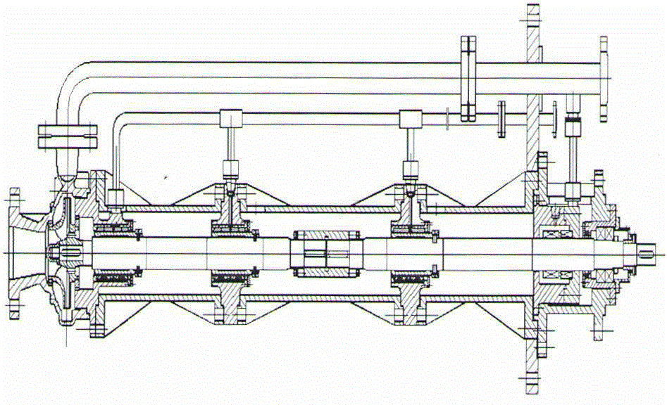
technical field [0001] The present invention relates to submerged pumps, and more particularly to magnetic drive submerged pumps. Background technique [0002] The submerged pump is to immerse the impeller and pump body parts in the conveyed medium. The medium is generally placed in a container or a pit, and the motor drive mechanism is located above the foundation. It is a special vertical pump and is widely used in power plants. , metal smelting, chemical process and sewage treatment and other fields. [0003] The existing submerged pump has a centrifugal submerged pump, and its structure is as attached figure 1 As shown, it includes a pump body, impeller, pump cover, pump shaft, and shaft frame tube. The shaft frame tube can be composed of multi-section butt joint connections, and bearing seat plates and bearings are provided on the butt ends of the two shaft frame tubes. The pump shaft can be It is composed of two or more butt joints. The bearings are ceramic sliding b...

Claims


Application Information

Patent Timeline
IPC IPC(8): F04D13/02F04D29/049F04D29/10
Inventor 赵强杨德乾马伟利林伟光唐志坚于国鑫王锋何德贵许斌滕朋李景涛窦文强佟有德冷旭
Owner 丹东克隆先锋泵业有限公司
Learn More