
Electrorheological fluid visualization testing stand

A technology for electrorheological fluids and test benches, which is applied in the fields of flow characteristics, measuring devices, instruments, etc., which can solve the problem that no structure and mechanical properties can be investigated and discussed at the same time, dynamic behavior has not been reported, and motion laws and structural evolution have not been carried out. investigation, etc.

Inactive Publication Date: 2014-02-26
XIANGTAN UNIV
View PDF2 Cites 10 Cited by
  • Summary
  • Abstract
  • Description
  • Claims
  • Application Information

AI Technical Summary

Problems solved by technology

[0004] At present, most studies on the microstructure of electrorheological fluids under the action of external fields focus on theoretical prediction methods such as numerical simulation, and the existing experimental devices and programs mainly focus on the observation of static fields. For dynamic fields, especially multi-field The dynamic behavior and microstructure under coupled effects are hardly reported
At the same time, during the observation, the evolution of the microstructure over time in a fixed area is observed, and the movement law and structural evolution of a certain part of the particles or a certain microcluster over time have not been investigated.
Secondly, in the previous experiments, the evolution process of its structure was observed separately or its mechanical properties were tested separately, and there was no experimental device to investigate its structure and mechanical properties at the same time and explore the internal relationship between the two.

Method used


Image

  • Electrorheological fluid visualization testing stand
  • Electrorheological fluid visualization testing stand
  • Electrorheological fluid visualization testing stand

Examples


Embodiment Construction

[0015] The present invention will be further described below in conjunction with the accompanying drawings.

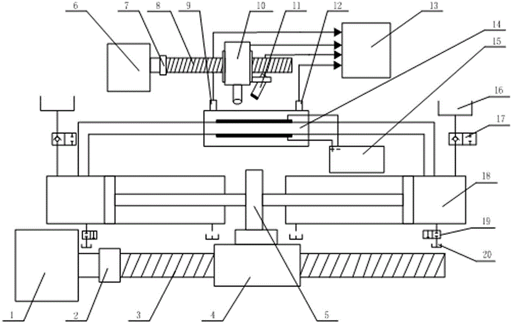
[0016] like figure 1 Shown, the present invention comprises stepping motor 1, leading screw 3, the second stepping motor 6, the second leading screw 8, two oil cylinders 18, electrorheological valve 14, signal acquisition and converter and computer 13; The motor 1 is connected with the lead screw 3 through the coupling 2, the lead screw 3 is provided with a lead screw nut 4, the lead screw nut 4 is fixedly equipped with a baffle 5, and the two ends of the baffle 5 are connected with the two oil cylinders 18 respectively. The piston rods of the two oil cylinders 18 are relatively arranged, and the centerlines of the piston rods of the two oil cylinders 18 are respectively parallel to the centerline of the leading screw 3; the bottoms of the two oil cylinders 18 communicate with the electrorheological valve 14 through conduits. The bottoms of the two oil cylinders 18 ar...


PUM


Abstract

The invention discloses an electrorheological fluid visualization testing stand. The electrorheological fluid visualization testing stand comprises a stepping motor, a lead screw, two oil cylinders, an electrorheological valve, a signal acquisition and conversion device and a computer. The stepping motor is connected to the lead screw by a coupling. The lead screw is provided with a lead screw nut. A baffle plate is fixedly installed on the lead screw nut. The baffle plate is connected respectively to piston rods of the two oil cylinders. The piston rods of the two oil cylinders are arranged oppositely. The center lines of the piston rods of the two oil cylinders are parallel to the center line of the lead screw. Bottoms of the two oil cylinders are communicated respectively with the electrorheological valve by conduits. Two ends of the electrorheological valve are provided respectively with pressure sensors. A digital microscope and an infrared temperature sensor are located at the position of the electrorheological valve. The pressure sensors, the digital microscope and the infrared temperature sensor are connected respectively with the computer by the signal acquisition and conversion device. The electrorheological fluid visualization testing stand can realize control on different dynamic fields, recording of a change of parameters such as pressure and temperatures, and on-line image acquisition and processing on an electrorheological fluid field microscopic dynamic structure.

Description

[0001] technical field [0002] The invention relates to an electrorheological fluid test device, in particular to a visual test bench for electrorheological fluid. Background technique [0003] Electrorheological fluid (ERF) is a two-phase suspension whose viscosity can be significantly increased under the action of an external electric field. It is generally believed that the change is due to the polarization of tiny dielectric particles dispersed in the ER fluid into electric dipoles under the action of an electric field, and the strong electrostatic attraction between these dipoles causes the change of the liquid's macroscopic viscosity. During this process, the particles change from disordered random distribution to ordered arrangement, usually forming a certain chain and columnar microstructure, which determines the macroscopic mechanical properties of the electrorheological fluid. [0004] At present, most studies on the microstructure of electrorheological...

Claims


Application Information

Patent Timeline
Patent Type & Authority Applications(China)
IPC IPC(8): G01N11/00
Inventor 朱石沙唐涛
Owner XIANGTAN UNIV
Learn More