Method for measuring electric conduction loop resistance of circuit breaker

A technology of loop resistance and conductive loop, applied in the direction of measuring resistance/reactance/impedance, measuring electrical variables, measuring devices, etc., can solve problems such as poor contact between wire clips and circuit breakers, prolonged power outages, and staff falling from high altitudes, etc. Achieve the effect of improving work efficiency and economic benefits, avoiding accidents and reducing power outages

Inactive Publication Date: 2014-02-26
STATE GRID CORP OF CHINA +1
View PDF2 Cites 25 Cited by
  • Summary
  • Abstract
  • Description
  • Claims
  • Application Information

AI Technical Summary

Problems solved by technology

[0006] Existing problems: (1) For circuit breakers with high voltage levels, such as 110kV, 220kV, 500kV, etc., because the circuit breakers are relatively high, it is too troublesome to perform item 1); (2) It is not safe for the staff to remove and install the lead wires (climbing operation), which may cause the staff to fall from high altitude; (3) The case of the circuit breaker (porcelain bottle) may be easily damaged by the staff if they are not careful; (4) When the staff connects the equipment clamps of the lead wires, carelessness causes the clamps to contact the circuit breaker Not good, it will overheat and even burn out after the power is turned on
[0008] Existing problems: (1) After the w...

Method used


Image

  • Method for measuring electric conduction loop resistance of circuit breaker
  • Method for measuring electric conduction loop resistance of circuit breaker

Examples


Embodiment Construction

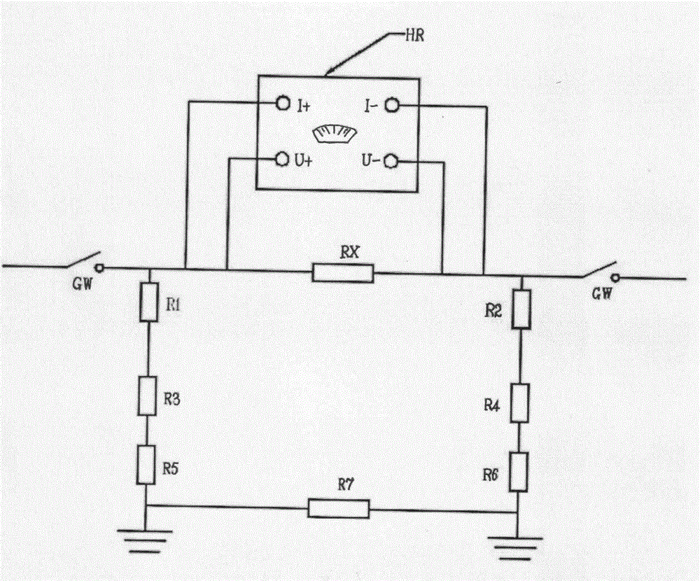
[0014] Attached figure 1 In the test method shown, without removing the grounding wires on both sides of the circuit breaker, directly connect the + , U+ are connected to one side of the tested resistance RX, and I- and U- of the HR loop resistance tester are connected to the other side of the tested resistance RX for testing.

[0015] The current misunderstanding of the circuit breaker conductive loop resistance test is: when performing a normal test, the grounding wires on both sides of the RX must be removed. It is considered that the grounding wires should not be removed. When the HR loop resistance tester outputs current, because the HR shell is grounded, current will flow through I + -R1-R3-R5-R7-R6-R4-R2-I ﹣ Flow back to HR loop resistance tester or directly to ground without flowing through RX.

[0016] Attached below figure 1 , 2 Describe the circuit breaker loop resistance test without disconnecting the ground wire. Such as figure 1 As shown in Fig. 1 , it is ...


PUM


Abstract

A method for measuring the electric conduction loop resistance of a circuit breaker is provided. The method comprises the following steps that: with grounding wires at two sides of the circuit breaker being not dismantled, I+ and U- of an HR loop resistance tester are directly connected with one side of a measured resistor RX; I- and U- of the HR loop are resistance tester are connected with the other side of the measured resistor RX; and then, testing is performed. According to the method for measuring the electric conduction loop resistance of the circuit breaker, self resistance of the grounding wires at the two sides of the circuit breaker, equipment grounding downlead resistance values, resistance values generated by frequent contact are far more larger than the resistance value of a switching-on loop inside the circuit breaker; equipment wire clamps at the two sides of the circuit breaker, which are connected with high-voltage leads, do not need to be dismantled; high-altitude?ascending and operation are not required; it does not need to dispatch and report to a work ticket signer and a work ticket licensor as well as apply to the work ticket signer and the work ticket licensor for dismantling the grounding wires at the two sides; testing can be accurately and fast performed on the electric conduction loop resistance of the circuit breaker (switch); and the method can assist in greatly shortening testing time, and greatly reducing outage time and significantly improving work efficiency and economic benefits.

Description

technical field [0001] The invention relates to a method for measuring the resistance of a conductive loop of a circuit breaker without removing the ground wires on both sides of a switch. Background technique [0002] In the power system, the circuit breaker (switch) is an important electrical equipment. National standard: GB50150-2006 "Electrical Equipment Handover Test Standard for Electrical Installation Engineering", Electric Power Industry Regulations DL / T596-1996 "Preventive Test Procedures for Electric Equipment" and State Grid Corporation's regulations Q / GDW 168-2008 "Condition Maintenance Test Regulations for Power Transmission and Transformation Equipment" all stipulate that when performing routine tests, regular inspections, preventive tests, and diagnostic tests on circuit breakers (switches), it is necessary to measure The loop resistance (contact resistance) between its moving and static contacts in the closing state is very important for its safe operation. ...

Claims


Application Information

Patent Timeline
IPC IPC(8): G01R27/08
Inventor 李明李昆高世伟
Owner STATE GRID CORP OF CHINA
Why Eureka
Try Eureka