Sonar image splicing method

An image mosaic and image technology, applied in image enhancement, image data processing, instruments, etc., can solve the problems of few feature points and large errors in sonar images

Inactive Publication Date: 2014-02-26
SHANGHAI UNIV
View PDF4 Cites 20 Cited by
  • Summary
  • Abstract
  • Description
  • Claims
  • Application Information

AI Technical Summary

Problems solved by technology

However, the background of the sonar image is seawater. If there are no other detection objects with significant feature points, the sonar image contains relatively few feature points.
If you use the image stitching method based on feature points to stitch sonar images with fewer feature points, there will be a large error

Method used


Image

  • Sonar image splicing method
  • Sonar image splicing method
  • Sonar image splicing method

Examples


Embodiment 1

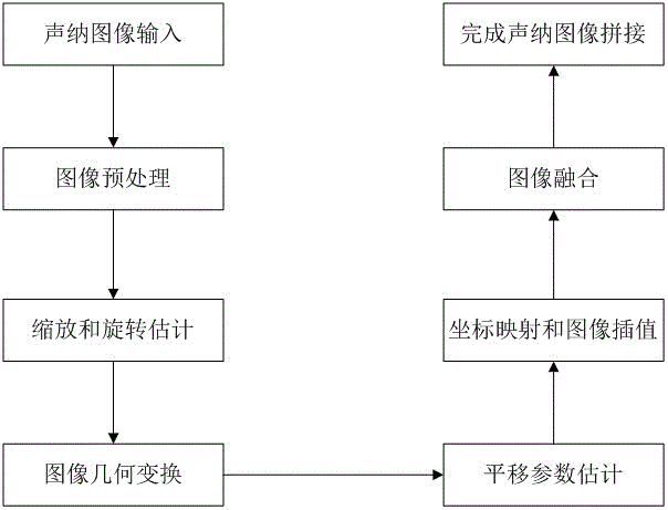
[0092] see figure 1 , the operation steps of the sonar image stitching method are as follows:

[0093] 1. Sonar image input

[0094] Reading sonar images is the same as reading general images; select the first frame image as the reference image , the second frame image is used as the image to be matched ; The relationship between the two input images is shown in formula (1);

[0095] 2. Image preprocessing

[0096] (1) Use Gaussian smoothing to remove Gaussian noise in the sonar image;

[0097] (2) Improve the contrast of the sonar image by stretching the image in gray scale;

[0098] 3. Scale and Rotation Estimation

[0099] Transform the scaling and rotation parameters into translation parameters by performing logarithmic polar coordinate transformation on the magnitude spectrum of the sonar image, and perform a phase correlation-based algorithm to obtain the scaling and rotation parameters;

[0100] (1) Image spectrum calculation

[0101] Perform Fourier transform...

Embodiment 2

[0130] This implementation is basically the same as implementation 1, the special features are:

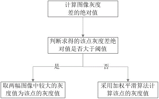
[0131] The operation steps of said step 7 image fusion include as follows:

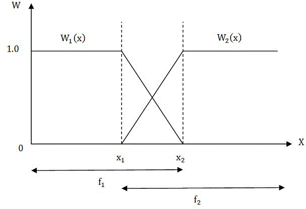
[0132] A threshold-based weighted smoothing algorithm is used to achieve the fusion of sonar images: for two adjacent frames of forward-scan sonar images with a small viewing angle range, under normal circumstances, due to the difference in sampling time and sampling angle, uneven brightness will appear in the overlapping part In order to make the overlapping parts of two adjacent images visually consistent and have no obvious seams, this scheme uses the image histogram normalization algorithm to adjust the brightness of the image to be matched, so that the brightness distribution of the image to be matched Consistent; and a threshold-based weighted smoothing algorithm is used to achieve the fusion of registered images.

[0133] Such as image 3 as shown, , are two adjacent sonar images to be splice...


PUM


Abstract

The invention relates to a sonar image splicing method. The method comprises the steps of removing noise in order to increase the contrast ratio through image preprocessing; transforming a scaling parameter and a rotation parameter into translation parameters through carrying out log-polar transformation to an image amplitude frequency spectrum, and carrying out algorithm analysis based on phase correlation; filtering scale and rotation factors through image geometric transformation; working out the translation parameters through an algorithm based on the phase correlation; and carry out coordinate mapping through the scaling parameter, the rotation parameter and the translation parameters which are worked out, and carrying out image interpolation through a bilinear interpolation algorithm. The registration of all sonar images is achieved by continuously repeating the above steps, then the splicing of the sonar images is achieved through brightness adjustment and image superposed area fusion. According to the invention, the problem that the detection scope visual angle of sonar is narrow in an underwater monitoring process is solved, through sonar image splicing, a series of sonar images are spliced to a large-scale sonar image, and therefore the sonar can simultaneously monitor a large-scale underwater environment.

Description

technical field [0001] The invention relates to a sonar image splicing method, in particular to a sonar image splicing method with fewer feature points. Background technique [0002] For underwater detection, due to the lack of natural light and very low visibility, traditional optical imaging is limited to a certain extent. Compared with optical imaging, sonar imaging systems can perform imaging underwater with low visibility and turbid water quality. So sonar imaging system is widely used in underwater detection. [0003] When the underwater observation object is relatively large and the resolution must be guaranteed, the transmitted signal cannot cover the entire detection area, and only local detection can be performed. At the same time, in terms of sonar image processing, the field of view of the acoustic detection area returned by an acoustic imaging is small, and it is often impossible to perform target recognition through an image in engineering practice. These pr...

Claims


Application Information

Patent Timeline
Patent Type & Authority Applications(China)
IPC IPC(8): G06T5/50
Inventor 何旭栋谢少荣朱方文罗均陈金波李恒宇王宇驰刘恒利黄潮炯吕所军翟飞跃
Owner SHANGHAI UNIV
Why Eureka
Try Eureka