
Neutral point potential balancing control system and method of three-level inverter

A technology of three-level inverter and potential balance, which is applied in the direction of control/regulation system, regulation of electrical variables, instruments, etc. It can solve problems such as fast dynamic response, increased hardware investment, unbalanced capacitor voltage, etc., to improve system performance , Improve the system response ability, reduce or suppress the effect of fluctuation

Inactive Publication Date: 2014-02-26
UNIV OF SHANGHAI FOR SCI & TECH
View PDF7 Cites 23 Cited by
  • Summary
  • Abstract
  • Description
  • Claims
  • Application Information

AI Technical Summary

Problems solved by technology

[0005] The present invention aims at the problem of the midpoint voltage fluctuation of the DC side of the three-level inverter, and proposes a three-level inverter midpoint potential balance control system and method. Compared with the traditional three-level inverter, only Added hardware input of two switch tubes and two diodes
The control method has high precision and can effectively solve the voltage imbalance problem of the two capacitors on the DC side of the three-level inverter, so that the three-level inverter can run smoothly and safely. At the same time, the dynamic response of the system is fast, and the circuit topology and control method are easy to implement.

Method used


Image

  • Neutral point potential balancing control system and method of three-level inverter
  • Neutral point potential balancing control system and method of three-level inverter
  • Neutral point potential balancing control system and method of three-level inverter

Examples


Embodiment Construction

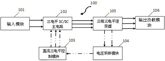
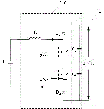
[0022] Such as figure 1 A schematic diagram of the connection of functional modules of a three-level inverter based on three-level DC / DC is shown, and a midpoint potential balance control system 100 of a three-level inverter includes: an input module 101, a three-level DC / DC main Circuit 102 , DC three-level control module 103 , voltage sampling module 104 , three-phase three-level inverter 105 , and output load module 106 .

[0023] The system collects the DC bus voltage of the three-phase three-level inverter 105 and the midpoint voltage of the two capacitors on the DC side in real time through the voltage sampling module 104, and sends them to the DC three-level control module 103 to generate corresponding control quantities; according to the obtained control quantities Determine the working mode of the system and the corresponding switching state of the switching tube, and at the same time meet the constraints of the midpoint potential determined by the ratio of the off t...


PUM


Abstract

The invention relates to a neutral point potential balancing control system and method of a three-level inverter. The neutral point potential balancing control system and method are used for conducting effective balancing control over the neutral point potential of the high-power diode clamped three-level inverter and collecting the DC bus voltage of the three-level inverter and the neutral point voltage value of two capacitors on the DC side in real time, sending collected signals to two independent PI regulators to generate corresponding controlled quantities, determining the operating mode of the system and the corresponding on-off state of switching tubes according to the obtained controlled quantities, determining the neutral point potential by the way of meeting the requirement of the turn-off time ratio of switching devices at the same time, determining the constraint condition of a busbar voltage according to the sum of connecting time, and accordingly adjusting the duty ratio of two switching tubes in an improved three-level DC / DC module, and therefore the busbar voltage on the DC side is controlled so that the dynamic voltage-sharing process of two supporting capacitors on the DC side can be achieved. Fluctuation of the neutral point potential of the three-level inverter is effectively reduced or restrained ultimately, system performance is improved, and the responsiveness of the system and the stability of a three-level topology circuit are improved.

Description

technical field [0001] The invention relates to a power electronic technology, in particular to a three-level inverter midpoint potential balance control method based on a three-level DC / DC. Background technique [0002] Compared with the traditional two-level inverter, the multi-level inverter has the advantages of low withstand voltage of switching devices, small output voltage harmonics, and low switching frequency, so it has been increasingly used in high-power applications in power electronics. Wide range of applications. The three-level inverter is the most widely used one because of its mature topology. [0003] Due to the unique structure and control strategy of the three-level inverter topology, the circuit has the problem of the midpoint voltage offset of the DC side capacitor. This problem will increase the low-order harmonics output by the system, reduce the efficiency, and shorten the life of the capacitor on the DC side in severe cases, and even cause overvol...

Claims


Application Information

Patent Timeline
IPC IPC(8): H02M7/483H02M3/155
Inventor 夏鲲李肖迪葛越袁印苗森丁晓波
Owner UNIV OF SHANGHAI FOR SCI & TECH
Learn More