Mixing attenuation control circuit in motor drive chip

A motor drive chip, attenuation control technology, applied in the direction of motor generator control, control system, electrical components, etc., can solve the problems of increasing the difficulty and cost of PCB design, reduce design cost, reduce design difficulty, reduce Effect of Peripheral Resistors

Active Publication Date: 2014-02-26
JIAXING ZHONGRUN MICROELECTRONICS
View PDF7 Cites 19 Cited by
  • Summary
  • Abstract
  • Description
  • Claims
  • Application Information

AI Technical Summary

Problems solved by technology

The main disadvantage of the traditional mixed decay mode control circuit is the external resistance, capacitance and voltage source Vd, which increases the difficulty and cost of PCB (Printed Circuit Board) design

Method used


Image

  • Mixing attenuation control circuit in motor drive chip
  • Mixing attenuation control circuit in motor drive chip
  • Mixing attenuation control circuit in motor drive chip

Examples


Embodiment Construction

[0029] Below in conjunction with accompanying drawing, the embodiment of the present invention is described in detail: present embodiment implements under the premise of the technical scheme of the present invention, has provided detailed implementation and specific operation process, but protection scope of the present invention is not limited to the following the embodiment.

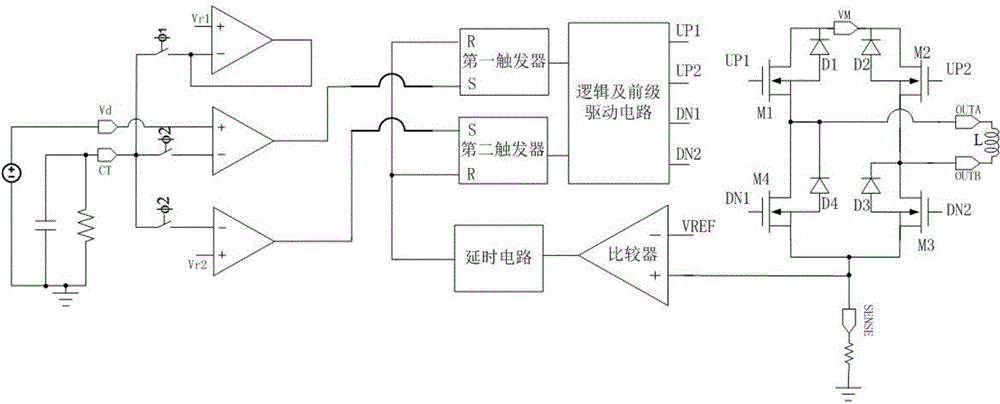
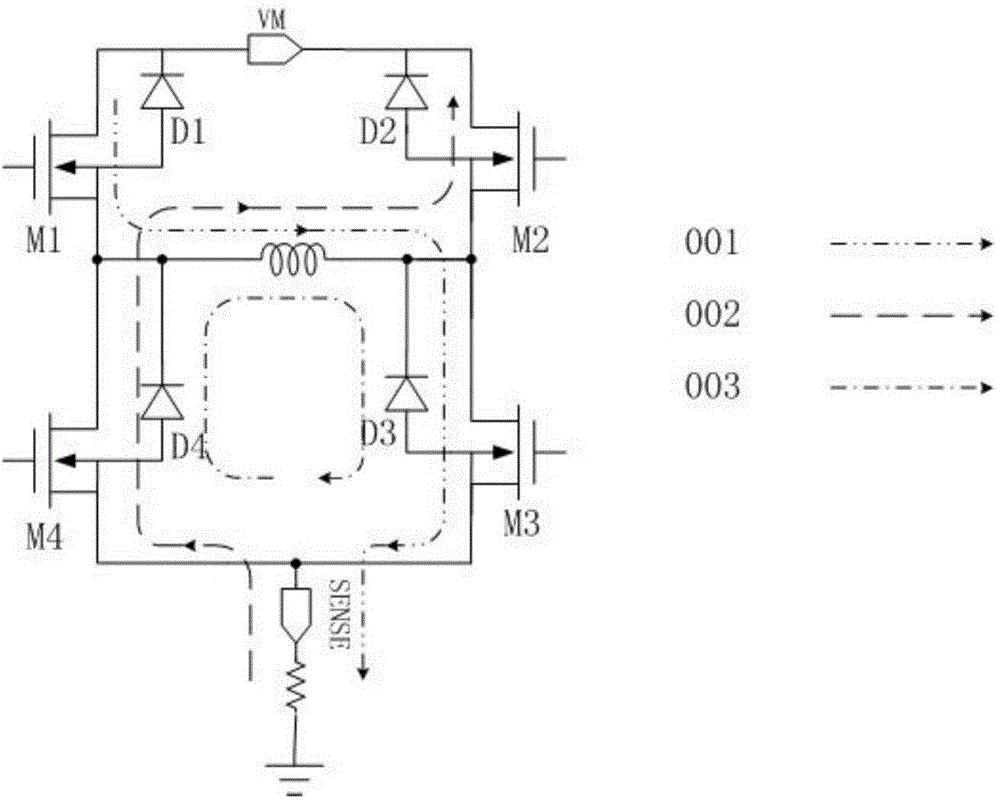
[0030] A mixed attenuation control circuit for a motor drive chip of the present invention includes an oscillator, a counter, a comparator, a first flip-flop, a second flip-flop, a logic and a pre-stage drive circuit, a current detection circuit, an H-bridge output stage, and an inductive load. The inductive load is connected to the output terminals OUTA and OUTB of the H-bridge output stage; the node A between the two symmetrical power devices of the H-bridge output stage is respectively connected to the current detection circuit and the first input terminal of the comparator; the first input terminal...


PUM


Abstract

A mixing attenuation control circuit in a motor drive chip comprises an oscillator, a counter, a comparator, a time delay circuit, a first trigger, a second trigger, a logic and preceding-stage drive circuit, a current detection circuit, an H-bridge output stage and an inductive load. The inductive load is connected with the output end of the H-bridge output stage, the H-bridge output stage and the current detection circuit are connected with the input end of the comparator, an output signal of the time delay circuit controls the oscillator, the counter, the first trigger and the second trigger to reset, an output signal of the counter triggers the first trigger and the second trigger so as to control quick attenuation time and slow attenuation time in a mixing attenuation mode of motor coil currents, and an output signal of the logic and preceding-stage drive circuit controls the H-bridge output stage, so that the inductive load is under a charging or attenuation stage. The mixing attenuation control circuit improves control accuracy of currents, improves system stability and reduces design difficulty and design cost of a printed circuit board (PCB).

Description

technical field [0001] The invention relates to a mixed attenuation control circuit, in particular to a mixed attenuation control circuit of a motor coil current in a motor drive chip. Background technique [0002] Current motors, especially stepper motors, need to detect the current in the coil in order to realize chopper constant current drive. When the set current is reached, the drive circuit will control the coil current to enter the decay stage. Currently, there are three modes for controlling current decay: slow decay mode, fast decay mode and mixed decay mode. In the slow decay mode, the voltage difference between the two ends of the coil is basically 0, the current decays very slowly, the cycle is very long, and a large audible noise is introduced; at the same time, when the set current drops, the actual current in the coil is often greater than the set value, causing the motor to The angle subdivision function fails and cannot be accurately positioned. In the fas...

Claims


Application Information

Patent Timeline
Patent Type & Authority Applications(China)
IPC IPC(8): H02P8/12
Inventor 夏存宝王良坤朱铁柱张明星陈路鹏黄武康
Owner JIAXING ZHONGRUN MICROELECTRONICS
Why Eureka
Try Eureka