Separation bed for differential type pneumatic dry separator, dry separator main machine and complete device

A differential and sorting technology, applied in the direction of solid separation, separation of solids from solids with airflow, chemical instruments and methods, etc., can solve the problems of limited scale expansion, high requirements for particle size, moisture, and low investment. , to achieve high transmission efficiency, long wear life and good antifouling performance

Active Publication Date: 2014-03-05
TANGSHAN KAIYUAN TECH
View PDF6 Cites 3 Cited by
  • Summary
  • Abstract
  • Description
  • Claims
  • Application Information

AI Technical Summary

Problems solved by technology

[0002] The cost of wind dry separation is low, the investment is small, and the effect is quick, so it develops rapidly. However, the current wind dry separation equipment has the following problems. Particle size and moisture are greatly affected, and the sorting effect is average; some equipment has a large investment in infrastructure and is inconvenient to maintain
Some equipments have high processing costs, too high requirements on the particle size and water content of the incoming materials, are not easy to operate, and cannot be applied to actual production; some equipment configurations are not compact enough, and the expansion scale is limited
Under the aforementioned circumstances, a new type of differential dry separator has been studied in recent years, which is currently widely used in industry, but it has not been well summarized in theory and practical operation, and there are still some problems

Method used


Image

  • Separation bed for differential type pneumatic dry separator, dry separator main machine and complete device
  • Separation bed for differential type pneumatic dry separator, dry separator main machine and complete device
  • Separation bed for differential type pneumatic dry separator, dry separator main machine and complete device

Examples


Embodiment Construction

[0033] The present invention will be described in detail below in conjunction with the accompanying drawings and embodiments.

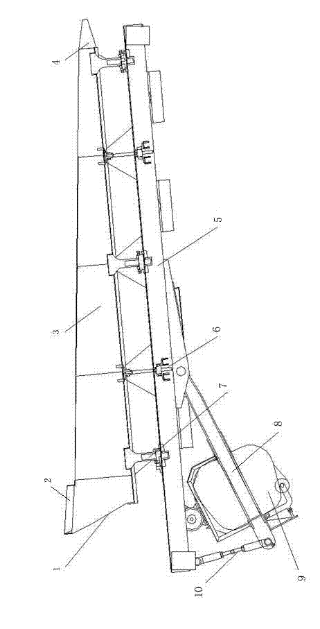
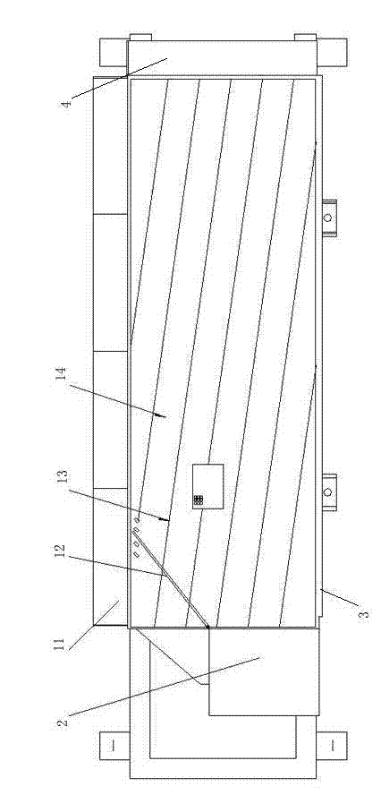
[0034] The sorting bed for this kind of differential air dry separation machine disclosed in the present invention comprises a rectangular sorting bed box 1, and the sorting bed box 1 is connected with the transmission frame 5 through an adjustment connecting device, and one end of the transmission frame is The bottom of the vibrator 9 is equipped with. The two ends of the sorting bed are the feed port 2 and the discharge port 4 respectively, and the discharge port is the discharge port for heavy materials; the discharge baffle 11 and the back plate 3 respectively constitute the two long sides of the rectangular box, and the discharge port The baffles 11 are respectively the baffles on the light material discharge port and the intermediate material discharge port. The bottom surface of the sorting bed box is composed of multiple rectangular sawtooth ...


PUM


Abstract

Provided is a separation bed for a differential type pneumatic dry separator. A separation bed box body is connected with a transmission frame through an adjustment connection device, and a vibration exciter is installed at the bottom at one end of the transmission frame. Two ends of the separation bed respectively serve as a feeding port and a discharging port, a discharging blocking plate and a back plate respectively serve as two long sides of the rectangular box body, the bottom face of the separation bed box body is formed by multiple rectangular zigzag rubber screening plates, and the separation bed is arranged obliquely. When the separation bed is oblique in the length direction of the separation bed, and a longitudinal included angle formed by the bottom face of the separation bed and a horizontal plane is 4-10 degrees. When the separation bed is oblique in the width direction of the separation bed, and a transverse included angle formed by the bottom face of the separation bed and the transmission frame is 4-8 degrees. The separation bed has the advantages of being compact in structure, simple and convenient to operate, good in abrasion resistance, high in friction coefficient, small in noise, long in service life, stable in transmission, simple and convenient to maintain and good in antifouling property, having no need for lubrication and the like.

Description

technical field [0001] The invention relates to a wind separation equipment, in particular to a sorting bed of a differential air dry separation machine for separating two or more mixed materials with large specific gravity differences in the fields of coal, metallurgy, building materials and agriculture, etc. Dry selection machine host and complete sets of equipment. Background technique [0002] The cost of wind dry separation is low, the investment is small, and the effect is quick, so it develops rapidly. However, the current wind dry separation equipment has the following problems. Particle size and moisture are greatly affected, and the sorting effect is average; some equipments require large investment in infrastructure and are inconvenient to maintain. Some equipments have high processing costs, too high requirements on the particle size and water content of the incoming materials, are not easy to operate, and cannot be used in actual production; some equipment conf...

Claims


Application Information

Patent Timeline
Patent Type & Authority Applications(China)
IPC IPC(8): B07B9/00
Inventor 任尚锦孙鹤
Owner TANGSHAN KAIYUAN TECH
Why Eureka
Try Eureka