Cantilever excavator capable of controlling posture of cutting head

A cantilever-type roadheader and cutting head technology, which is applied in the direction of cutting machinery, slitting machinery, driving devices, etc., can solve the problems that the attitude cannot be flexibly controlled, it is difficult to cut out a smooth roadway wall, and the driving efficiency is low. Achieve the effect of reducing the number of equipment and auxiliary operation time, reducing the workload of auxiliary finishing, and improving the efficiency of tunneling

Inactive Publication Date: 2014-03-05
HENAN POLYTECHNIC UNIV
View PDF6 Cites 3 Cited by
  • Summary
  • Abstract
  • Description
  • Claims
  • Application Information

AI Technical Summary

Problems solved by technology

Since the cutting head is fixedly connected to the cutting arm, the spatial posture of the cutting head is completely determined by the state of the telescopic arm and cannot be adjusted freely.
Since the rotation axis posture of the cutting head cannot be flexibly controlled, it is difficult for the outer envelope surface of the cutting head to completely fit the ideal roadway design wall, and it is difficult for the roadheader to cut a smooth and smooth roadway wall, and can only form a jagged roadway the wall
In severe cases, it may cause trouble to the support work, and surface modification must be carried out, which increases the extra workload
At the same time, the auxiliary functions of the roadheader, such as digging drainage ditches and column nests, are not ideal.
[0004] In addition, support, outburst prevention and other work are often required during roadway excavation. The existing cantilever roadheader can only complete the excavation and cutting work alone, and other tasks require additional configuration of various construction equipment. Construction often requires a lot of auxiliary work time such as handling, stabilization, adjustment, etc., and the excavation efficiency is low

Method used


Image

  • Cantilever excavator capable of controlling posture of cutting head
  • Cantilever excavator capable of controlling posture of cutting head
  • Cantilever excavator capable of controlling posture of cutting head

Examples


Embodiment Construction

[0021] The present invention will be further described in detail below in conjunction with the accompanying drawings and specific embodiments.

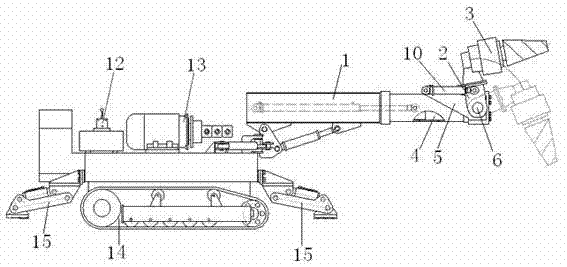
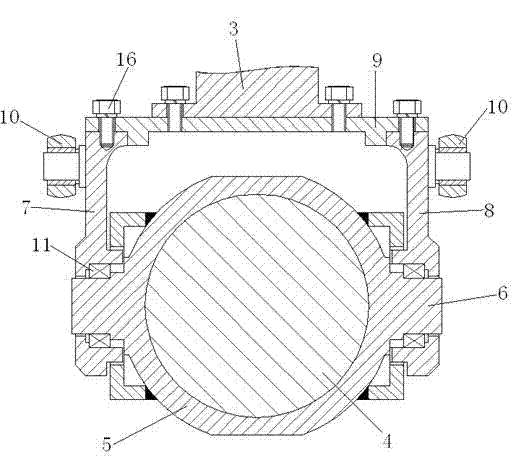
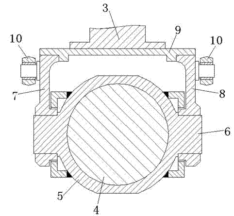
[0022] A cutting head posture controllable cantilever roadheader, such as figure 1 As shown, it includes a power system 13, a walking system 14, a hydraulic control system 12 and an auxiliary support system 15. The front part of the telescopic arm 1 of the roadheader includes a swing frame 2, a rotary hydraulic cylinder 4, a rotary cover 5, and a swing frame control hydraulic system. Cylinder 10 and hydraulic drive cutting head 3, wherein:

[0023] The rotary hydraulic cylinder 4 is fixedly installed on the extended end of the extendable part of the telescopic arm, and the axis of the rotary output shaft of the rotary hydraulic cylinder is consistent with the telescopic direction of the telescopic arm;

[0024] The rotary cover 5 is fixedly installed on the rotary output shaft of the rotary hydraulic cylinder 4, and the two sides of ...


PUM


Abstract

The invention discloses a cantilever excavator capable of controlling the posture of a cutting head, wherein the front of a telescopic arm (1) of the excavator comprises a swing frame (2), a rotary hydraulic cylinder (4), a rotary cover (5), a swing frame control hydraulic cylinder (10) and a hydraulic drive cutting head (3), wherein the rotary hydraulic cylinder is fixed at an extending end of an extending part of the telescopic arm; the rotary cover is fixed at a rotary output shaft of the rotary hydraulic cylinder; two lug shafts (6) are correspondingly arranged at the two sides of the rotary cover; the swing frame is controlled to rotate around the lug shafts by the swing frame control hydraulic cylinder; the hydraulic drive cutting head is connected with the swing frame. According to the cantilever excavator, the whole hydraulic drive cutting head can rotate around the axis vertical to a cutting arm, so that the space posture of the hydraulic drive cutting head can be freely controlled; the hydraulic drive cutting head is connected with the swing frame in a fixed or detachable way, so that other operation tools can be installed and replaced on the swing frame after the hydraulic drive cutting head is disassembled in the detachable connection way, more auxiliary operation functions can be realized by the excavator, and the excavation efficiency is improved.

Description

technical field [0001] The invention relates to a cantilever-type roadheader, the cutting head of which can realize the flexible adjustment of spatial posture under the action of a rotary hydraulic cylinder and a hydraulic cylinder of a swing frame assembly. Background technique [0002] The cantilever roadheader is a kind of excavation equipment widely used in tunnel and roadway excavation. The rotary motion of the cutting head installed on the front end of the cantilever drives the picks installed on the surface of the cutting head to strip and break coal or rock to realize the excavation construction. . The cutting head of the existing roadheader has two ways of installation along the axis of the telescopic arm and vertical installation. The axis of rotation of the cutting head and the axis of the telescopic arm are relatively fixed and cannot be adjusted freely. After the position of the roadheader is fixed, the up and down, left, and right swings of the telescopic arm ...

Claims


Application Information

Patent Timeline
Patent Type & Authority Applications(China)
IPC IPC(8): E21C25/00E21C31/00
Inventor 刘志忠刘建慧姬玉荣宋军陈小砖孟凡茂
Owner HENAN POLYTECHNIC UNIV
Why Eureka
Try Eureka