Intake manifold integrating oil-gas separation device with PCV, engine and automobile

A separation device, intake manifold technology, applied in the direction of engine components, machines/engines, engine lubrication, etc., can solve the problems of insignificant oil and gas separation effect, reduce connection pipelines, etc., so as to improve oil and gas separation efficiency and reduce connection. Pipelines and the effect of reducing the difficulty of engine room layout

Active Publication Date: 2014-03-05
GREAT WALL MOTOR CO LTD
View PDF5 Cites 6 Cited by
  • Summary
  • Abstract
  • Description
  • Claims
  • Application Information

AI Technical Summary

Problems solved by technology

[0007] In order to solve the above deficiencies in the prior art, the present invention provides an intake manifold integrating an oil-gas separation device and a PCV valve, which reduces the connecting pipelines inside the engine, makes the arrangement of parts inside the engine more compact, and can Reduce the difficulty of engine room layout; at the same time, it can solve the problem that the oil-gas separation effect is not obvious when the engine is running at low load, and can ensure the best oil-gas separation effect;

Method used


Image

  • Intake manifold integrating oil-gas separation device with PCV, engine and automobile
  • Intake manifold integrating oil-gas separation device with PCV, engine and automobile
  • Intake manifold integrating oil-gas separation device with PCV, engine and automobile

Examples


Embodiment 1

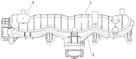
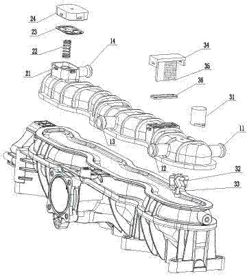
[0044] An intake manifold integrating an oil-gas separation device and a PCV valve, the structure of which is as follows Figure 1-2 As shown, it includes an intake manifold 4, a cover body 1, an oil-gas separation device, and a PCV valve 2.

[0045] The cover body 1 is fixed on one side of the main pipeline of the intake manifold 4 , and the inner cavity of the cover body 1 communicates with the inner cavity of the intake manifold 4 . One side of the cover body 1 is respectively provided with an air inlet pipe 11 , and the other side is provided with a first oil return pipe 12 and a second oil return pipe 13 .

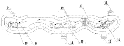
[0046] Such as image 3 As shown, the inner cavity of the cover body 1 is divided into a first chamber 15, a second chamber 16, and a steady flow chamber 17 which are sequentially connected, and their transverse sections are all trapezoidal structures with a large top and a small bottom. The first chamber 15 communicates with the intake pipe 11 and the first oil ret...

Embodiment 2

[0056] An engine, which differs from the prior art only in that the complex of the oil-gas separation device, the PCV valve and the intake manifold is the intake manifold of the integrated oil-gas separation device and the PCV valve provided in Embodiment 1.

[0057] The structure of other parts of this engine is identical with prior art.

Embodiment 3

[0059] A kind of automobile, the difference between this automobile and the prior art only lies in: the structure of its engine is completely the same as that of embodiment 2.


PUM


Abstract

The invention discloses an intake manifold integrating an oil-gas separation device with a PCV. The intake manifold comprises an intake manifold body, the oil-gas separation device and a cover, wherein the cover is fixed on one side of a main pipeline of the intake manifold body, and an inner cavity of the cover is communicated with an inner cavity of the main pipeline; the oil-gas separation device is arranged in the inner cavity of the cover; the cover is provided with an intake pipe used for making an oil-gas mixture enter the oil-gas separation device, and an oil return pipe used for collecting engine oil; the PCV provided with an exhaust pipe is further fixed on the cover. The invention further discloses an engine provided with the intake manifold and an automobile provided with the intake manifold. By means of the intake manifold integrating the oil-gas separation device with the PCV, the number of connecting pipelines inside the engine is reduced, and the arrangement of components and parts inside the engine is more compact; meanwhile, the problem that the oil-gas separation is not obvious when the engine runs at a low load can be solved. The intake manifold integrating the oil-gas separation device with the PCV is applicable to engines of various vehicles and is further applicable to various automobiles.

Description

technical field [0001] The invention belongs to the technical field of motor vehicles, and relates to an engine oil-gas separation device and an intake manifold, in particular to an intake manifold integrating an oil-gas separation device and a PCV valve, a corresponding engine and an automobile. Background technique [0002] During the operation of the engine, some incompletely combusted mixture mixed with engine oil and water vapor will escape from the combustion chamber into the crankcase. If these exhaust gases cannot be discharged in time, the pressure in the crankcase will be too high, resulting in engine leakage. Oil, engine oil deterioration and other problems, thus affecting engine performance and polluting the environment. [0003] The crankcase ventilation system of the engine is equipped with an oil-air separation device for separating the oil-air mixture. In the prior art, the oil-gas separation device mainly has the following methods: [0004] ①External oil-g...

Claims


Application Information

Patent Timeline
Patent Type & Authority Applications(China)
IPC IPC(8): F01M11/08
Inventor 郑宝龙孙青山孟凡兴沈吉瑞武永生
Owner GREAT WALL MOTOR CO LTD
Why Eureka
Try Eureka