
Continuous Regenerative Industrial Furnace Waste Heat Utilization System

An industrial furnace, regenerative technology, applied in furnaces, waste heat treatment, furnace components, etc., can solve the problems of discontinuous combustion, energy waste, environmental damage, etc., and achieve the effect of improving waste heat utilization efficiency and simplifying pipeline layout.

Inactive Publication Date: 2018-01-26
广东裕方建设工程有限公司
View PDF9 Cites 0 Cited by
  • Summary
  • Abstract
  • Description
  • Claims
  • Application Information

AI Technical Summary

Problems solved by technology

[0007] However, the technologies disclosed in the above three patents / patent applications all have the following shortcomings or deficiencies: (1) A pair of burners are respectively arranged on both sides of the furnace body, and a pair of regenerators / regenerators are used They are respectively arranged on both sides of the furnace body, and the equipment needs to stop running when switching the working state, so that the combustion is discontinuous; (2), the symmetrical layout scheme on both sides is adopted, which makes the pipeline layout complicated; (3), the flue gas flows from the storage After the heat chamber / regenerator is discharged, it still has some waste heat, which is directly discharged into the environment, which will still cause energy waste and cause a certain degree of damage to the environment

Method used


Image

  • Continuous Regenerative Industrial Furnace Waste Heat Utilization System
  • Continuous Regenerative Industrial Furnace Waste Heat Utilization System

Examples


Embodiment approach

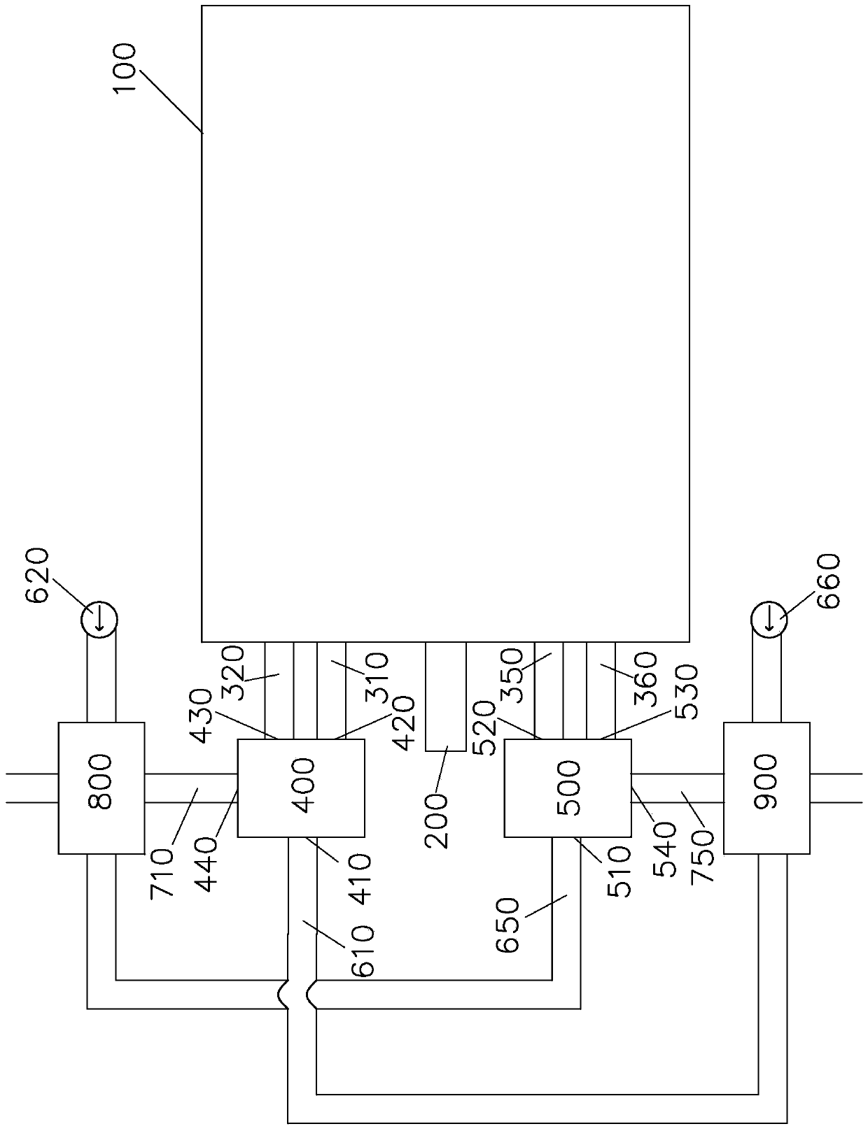
[0027] Please refer to figure 1 , according to an embodiment of the present invention, the continuous regenerative industrial furnace waste heat utilization system includes: a furnace body 100, a fuel nozzle 200, a first ventilation pipe 310, a second ventilation pipe 350, a first smoke exhaust pipe 320, a second The smoke exhaust pipe 360 ​​, the first heat storage 400 , the second heat storage 500 , the first air intake pipe 610 , the second air intake pipe 650 , the first smoke gas passage 710 and the second smoke gas passage 750 .

[0028] The furnace body 100 is provided with a furnace (not shown) for heating materials. The fuel nozzle 200 is arranged on one end wall of the furnace body 100 . The first air pipe 310 , the second air pipe 350 and the fuel nozzle 200 are arranged at equal intervals on the same end wall of the furnace body 100 . The first ventilation pipe 310 and the second ventilation pipe 350 communicate with the furnace gas respectively.

[0029] The fi...


PUM


Abstract

The invention discloses a waste heat utilization system of a continuous heat accumulating type industrial furnace. The waste heat utilization system comprises a furnace body, a fuel nozzle, a first breather pipe, a second breather pipe, a first smoke exhaust pipe, a second smoke exhaust pipe, a first heat reservoir, a second heat reservoir, a first air inlet pipe, a second air inlet pipe, a first smoke passageway and a second smoke passageway. The first breather pipe, the second breather pipe, the first smoke exhaust pipe and the second smoke exhaust pipe are arranged on the side end wall of the furnace body at intervals and communicated with a hearth. The first heat reservoir comprises a first port, a second port, a third port and a fourth port, wherein the first port is communicated with the first air inlet pipe, the second port is communicated with the first breather pipe, the third port is communicated with the first smoke exhaust pipe, and the fourth port is communicated with the first smoke passageway. The second heat reservoir comprises a first port, a second port, a third port and a fourth port, wherein the first port is communicated with the second air inlet pipe, the second port is communicated with the second breather pipe, the third port is communicated with the second smoke exhaust pipe, and the fourth port is communicated with the second smoke passageway. The first heat reservoir and the second heat reservoir can run alternately between the preheating state and the heat accumulating state.

Description

technical field [0001] The invention relates to an industrial furnace waste heat utilization system, in particular to a regenerative industrial furnace waste heat utilization system. Background technique [0002] In the face of increasingly severe environmental problems and energy crises, the whole world is vigorously advocating energy conservation and emission reduction, especially for industrial kiln related industries with serious energy consumption and pollution. Factors that personnel must consider when designing such equipment. [0003] Taking an aluminum melting furnace as an example, the flue gas temperature at the flue gas outlet usually reaches about 1000 degrees Celsius. If these high-temperature flue gases are directly discharged into the environment, it will not only cause energy waste but also cause a certain degree of damage to the environment. [0004] As disclosed in Chinese Patent No. 03244707.8, a low nitrogen oxide high-efficiency regenerative industria...

Claims


Application Information

Patent Timeline
Patent Type & Authority Patents(China)
IPC IPC(8): F27D17/00F28D15/02F23L15/04
CPCY02E20/34Y02P10/25
Inventor 方武冬刘效洲
Owner 广东裕方建设工程有限公司
Features
  • Generate Ideas
  • Intellectual Property
  • Life Sciences
  • Materials
  • Tech Scout
  • Unparalleled Data Quality
  • Higher Quality Content
  • 60% Fewer Hallucinations
Learn More