Fast switchover heat accumulating type aluminum smelting furnace

A fast-switching, heat-storing technology, applied in the field of aluminum melting furnaces, can solve problems such as discontinuous combustion, energy waste, and environmental damage, and achieve the effects of improving waste heat utilization efficiency, simplifying pipeline layout, and saving energy consumption

Inactive Publication Date: 2014-01-22
横琴东方智睿科技有限公司
View PDF8 Cites 0 Cited by
  • Summary
  • Abstract
  • Description
  • Claims
  • Application Information

AI Technical Summary

Problems solved by technology

[0008] However, the technologies disclosed in the above three patents / patent applications all have the following shortcomings or deficiencies: (1) A pair of burners are respectively arranged on both sides of the furnace body, and a pair of regenerators / regenerators are used They are respectively installed on both sides of the furnace body, and the equipment needs to stop running when switching the working state, so that the combustion is discontinuous; (2), the symmetrical layout scheme on both sides is adopted, which makes the pipeline layout complicated; (3), the flue gas flows from the storage After the thermal chamber / regenerator is discharged, it still has some waste heat, and if it is directly discharged into the environment, it will still cause energy waste and cause a certain degree of damage to the environment; (4), the regenerator / regenerator adopts a single structure, The effect of soot in the flue gas on the performance of the regenerator / regenerator is not considered

Method used


Image

  • Fast switchover heat accumulating type aluminum smelting furnace
  • Fast switchover heat accumulating type aluminum smelting furnace
  • Fast switchover heat accumulating type aluminum smelting furnace

Examples


Embodiment approach

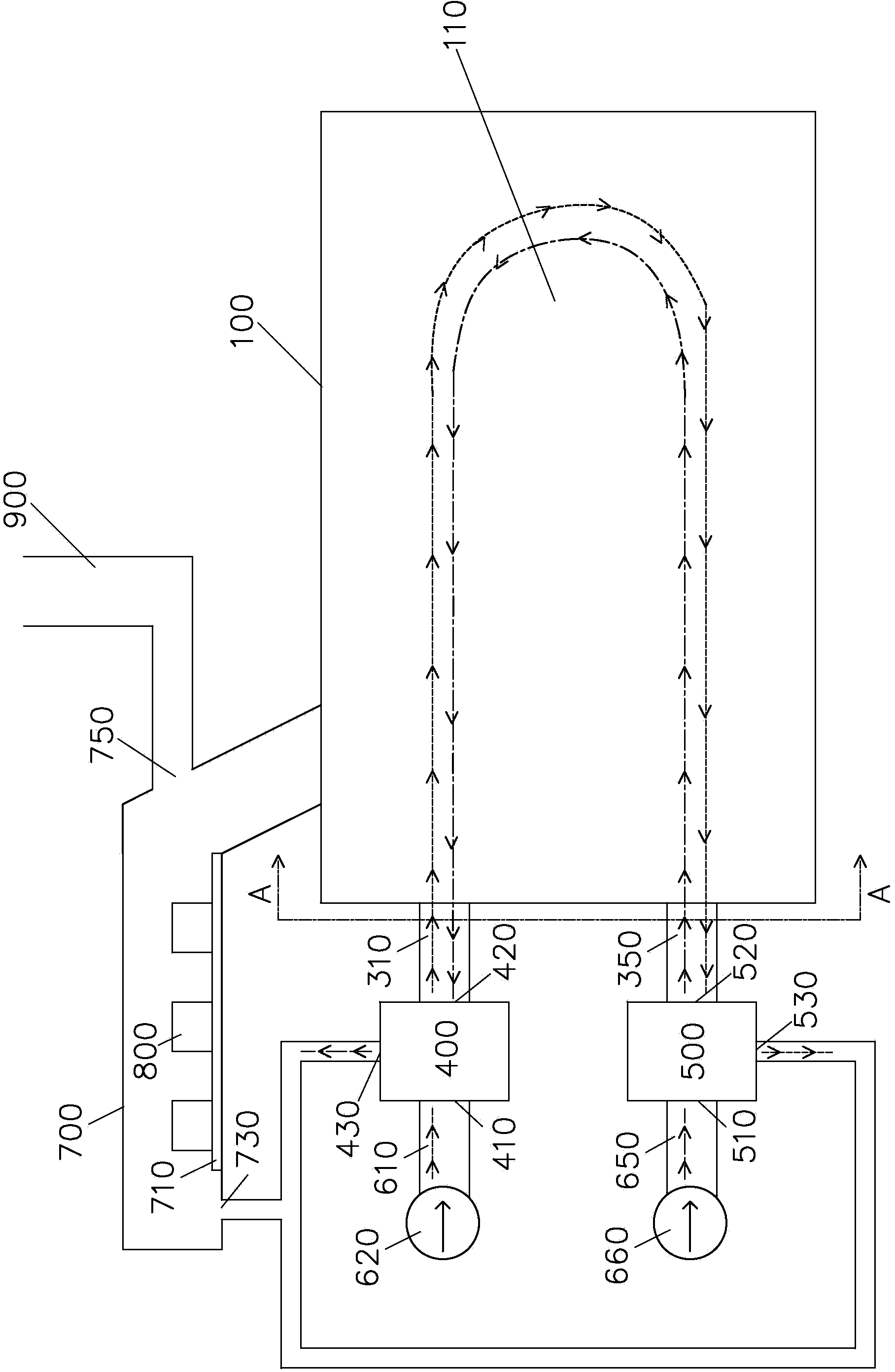
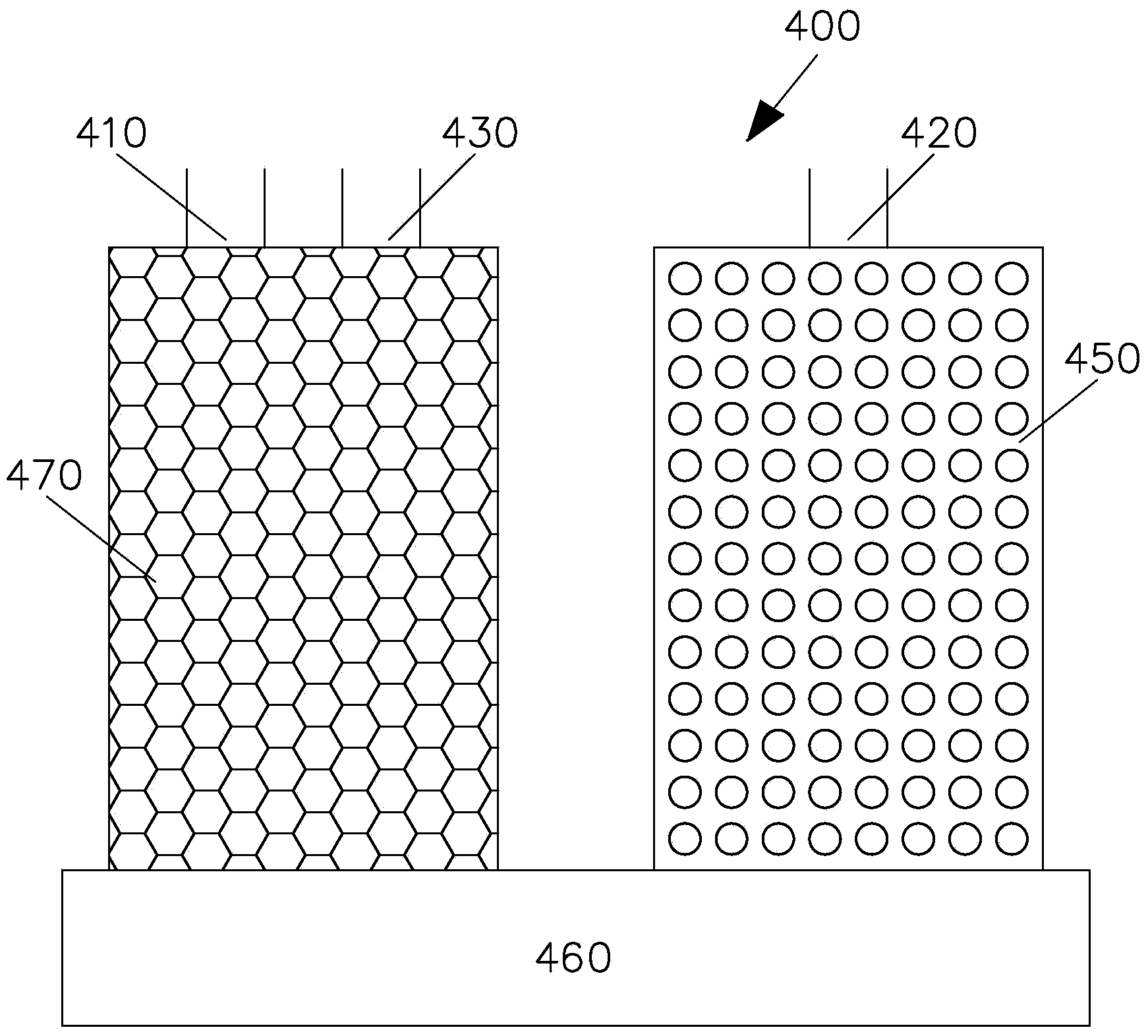
[0027] Please refer to figure 1 and figure 2 , according to an embodiment of the present invention, the fast switching regenerative aluminum melting furnace includes: a furnace body 100, a first fuel nozzle 210, a second fuel nozzle 250, a first ventilation pipe 310, a second ventilation pipe 350, a first The heat storage 400 , the second heat storage 500 , the first air intake pipe 610 , the second air intake pipe 650 and the aluminum material delivery channel 700 .

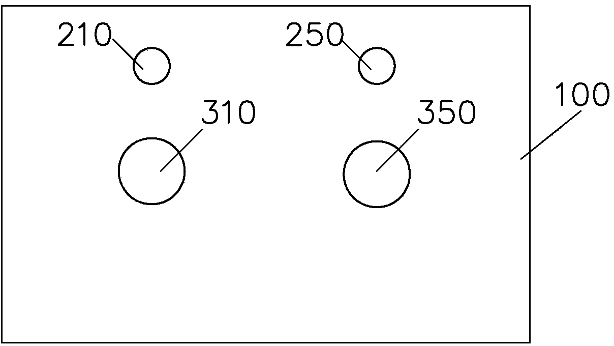
[0028] The furnace body 100 is provided with a furnace 110 for heating aluminum materials. The first fuel nozzle 210 and the second fuel nozzle 250 are spaced apart on one end wall of the furnace body 100 . The first air pipe 310 and the second air pipe 350 are disposed at intervals on the end wall of the same side of the furnace body 100 and are respectively located below the first fuel nozzle 210 and the second fuel nozzle 250 . The first ventilation pipe 310 and the second ventilation pipe 350 are in gas ...


PUM


Abstract

The invention discloses a fast switchover heat accumulating type aluminum smelting furnace which comprises a furnace body, a first fuel spray nozzle, a second fuel spray nozzle, a first vent pipe, a second vent pipe, a first heat reservoir, a second heat reservoir, a first air inlet pipe and a second air inlet pipe. The first vent pipe and the second vent pipe are arranged on the end wall of one side of the furnace body at intervals and are communicated with a combustion chamber, and the first vent pipe and the second vent pipe are located below the first fuel spray nozzle and the second fuel spray nozzle respectively. The first heat reservoir comprises a first port, a second port and a third port. The first port of the first heat reservoir is communicated with the first air inlet pipe, the second port of the first heat reservoir is communicated with the first vent pipe, and the third port of the first heat reservoir is communicated to a chimney through a pipeline. The second heat reservoir comprises a first port, a second port and a third port. The first port of the second heat reservoir is communicated with the second air inlet pipe, the second port of the second heat reservoir is communicated with the second vent pipe, and the third port of the second heat reservoir is communicated to the chimney through a pipeline. The first heat reservoir and the second heat reservoir are alternatively switched and run between a preheating working state and a heat accumulating working state.

Description

technical field [0001] The invention relates to an aluminum melting furnace, in particular to a regenerative waste heat recovery system of the aluminum melting furnace. Background technique [0002] In the face of increasingly severe environmental problems and energy crises, the whole world is vigorously advocating energy conservation and emission reduction, especially for industrial kiln related industries with serious energy consumption and pollution. Factors that personnel must consider when designing such equipment. [0003] Taking an aluminum melting furnace as an example, the flue gas temperature at the flue gas outlet usually reaches about 1000 degrees Celsius. If these high-temperature flue gases are directly discharged into the environment, it will not only cause energy waste but also cause a certain degree of damage to the environment. [0004] In addition, High Temperature Air Combustion (HTAC for short) has been widely promoted at home and abroad since the end ...

Claims


Application Information

Patent Timeline
Patent Type & Authority Applications(China)
IPC IPC(8): F27B14/14F27D17/00
Inventor 杨志文
Owner 横琴东方智睿科技有限公司
Why Eureka
Try Eureka