Check patentability & draft patents in minutes with Patsnap Eureka AI!

Intermediate rolling mill area of ​​the cast-rolling complex

A rolling compound, intermediate rolling mill technology, applied in metal rolling, metal rolling, metal processing equipment and other directions, can solve the problem of reducing equipment operation reliability, reducing investment and operating costs of casting and rolling compound equipment. and other problems, to achieve the effect of reducing the length of the structure, reducing the operating cost and improving the compactness

Active Publication Date: 2016-03-16
PRIMETALS TECH AUSTRIA GMBH
View PDF9 Cites 0 Cited by
  • Summary
  • Abstract
  • Description
  • Claims
  • Application Information

AI Technical Summary

Problems solved by technology

However, this can result in the casting having to be interrupted in the event of an interruption of the plant components downstream of the shears, which significantly reduces the operating reliability of the plant
How to reduce the structural length of the casting-rolling composite equipment and reduce the investment and operating costs of the casting-rolling composite equipment under the condition of relatively high operational reliability, this document does not propose

Method used


Image

  • Intermediate rolling mill area of ​​the cast-rolling complex
  • Intermediate rolling mill area of ​​the cast-rolling complex
  • Intermediate rolling mill area of ​​the cast-rolling complex

Examples


Embodiment Construction

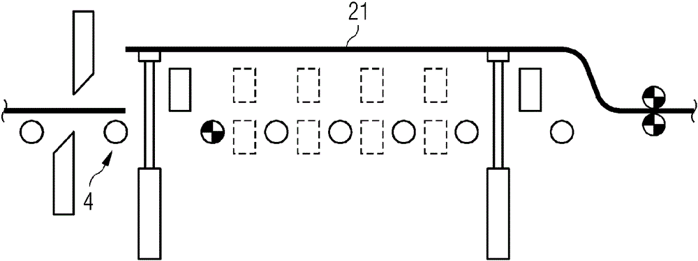
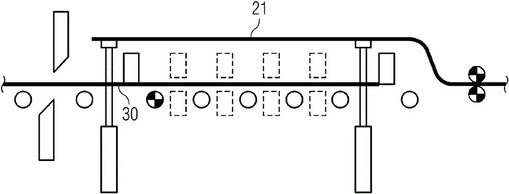
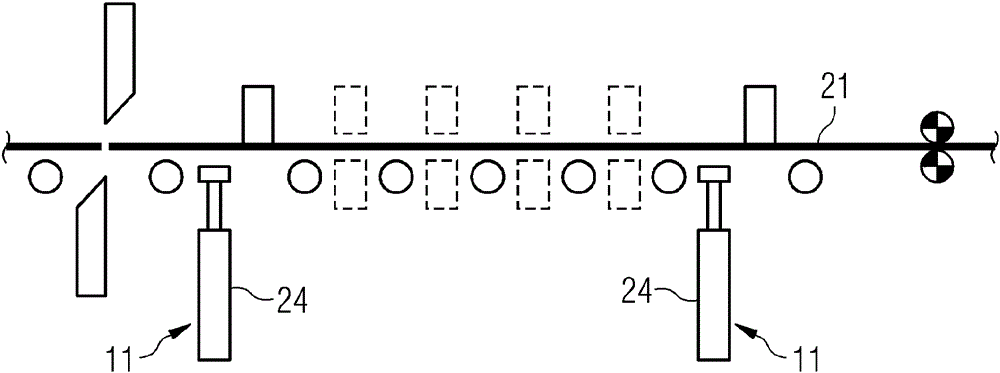
[0077] FIG. 1 shows a combined casting and rolling plant 1 known from WO 2009 / 121678 A1. In continuous operation, the continuous casting machine 2 continuously produces a precast material 3 in the form of thin-slab strands, which is conveyed via a roller table 4 to a roughing mill 5 . After rough rolling in the roughing mill 5, the roughed strip 30 is uncut, i.e. as a continuously cast slab, before it is hot-rolled into the finished strip 40 in a single-stand or multi-stand finishing mill 14 Through the intermediate mill zone Z comprising the induction furnace 12 and the descaling plant 13 . The finished strip 40 is then cooled in the cooling section 15 , cut to a defined product length or a defined product weight by a shear 16 and then coiled in a storage device 17 configured as a coiling device. The roller table 4 connects all equipment components between the horizontal continuous casting slab guide roller of the continuous casting machine 2 and the storage device 17; the c...


PUM

PropertyMeasurementUnit
lengthaaaaaaaaaa

Abstract

The system has a continuous casting machine for continuous casting of a strand of an endless starting material. An intermediate road area (Z) of scissors (9) cuts a strip (30). Unloading device (8) feeds the sliver section. An induction furnace heats the strip to a rolling temperature. Roller conveyor has rollers (31-33) arranged in a conveying direction. Cooling section cools a finished belt. Raising device (11) is arranged between first and second rollers (31,32). Unloading device is arranged between second and third rollers (32,33). Heating modules (12a) are arranged in furnace. An independent claim is included for casting plant.

Description

technical field [0001] The invention relates to the so-called intermediate rolling mill region of a cast-rolling complex, ie the region between a roughing stand and a finishing stand in a cast-rolling plant. [0002] One type of plant is known as a casting-rolling plant, in which a casting plant (for example a continuous caster or a two-roll caster with through-flow dies, rolling dies or crawler molds) is coupled to a rolling plant. The cast-rolling plant can be operated either in so-called continuous operation (English endless) or in so-called semi-continuous operation (English: semi-endless or batch), wherein in continuous operation the continuous casting produced by the casting plant The billets are processed uncut in the rolling plant to form hot-rolled products. Thus belonging to the cast-rolling combination plant are endless strip production lines ESP (Endless Strip Production), compact strip production lines CSP (Compact Strip Production) and so-called CSP-flex plants....

Claims


Application Information

Patent Timeline
Patent Type & Authority Patents(China)
IPC IPC(8): B21B1/46B21B15/00B22D11/12
CPCB21B1/24B21B1/463B22D11/1206B22D11/14F27B9/201B21B1/466B21B39/14B21B45/004B22D11/126
Inventor T.伦高尔W.培特R.温克勒
Owner PRIMETALS TECH AUSTRIA GMBH
Features
  • R&D
  • Intellectual Property
  • Life Sciences
  • Materials
  • Tech Scout
  • Unparalleled Data Quality
  • Higher Quality Content
  • 60% Fewer Hallucinations
Learn More