Device and method for recording pulse laser ablation dynamic changes

A dynamic change, laser ablation technology, applied in the field of laser applications, can solve problems such as errors, response time is not a constant value, laser response time cannot accurately determine the initial laser action time, etc., to achieve good ablation performance and improve ablation efficiency.

Active Publication Date: 2014-03-12
CHINA UNIV OF GEOSCIENCES (WUHAN)
View PDF7 Cites 9 Cited by
  • Summary
  • Abstract
  • Description
  • Claims
  • Application Information

AI Technical Summary

Problems solved by technology

However, in practical applications, due to the long response time of the laser (microsecond or even millisecond level) and the response time is not constant, the recorded dynamic process time will be inaccurate or even wrong.
In addition, if the pulse delay control generator is used to control the laser and the high-speed camera synchronously, although the complete dynamic change process can be recorded, the initial laser action time cannot be accurately determined due to the variability of the laser response time, resulting in the recording of the dynamic change process. precise

Method used


Image

  • Device and method for recording pulse laser ablation dynamic changes

Examples


Embodiment Construction

[0013] The present invention will be described in detail below in conjunction with specific examples, but the protection scope of the present invention is not limited to the following examples.

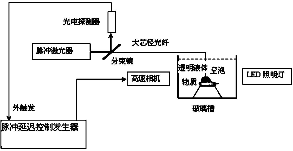
[0014] The structural block diagram of the device for recording pulsed laser ablation dynamic changes provided by the present invention is as follows: figure 1 As shown, it includes a photodetector, a beam splitter, a high-speed camera, a pulse delay control generator and an illuminating lamp, wherein the illuminating lamp is an LED lamp.

[0015] from figure 1 It can be seen from the middle view that the beam splitter is set on the laser emission line of the pulse laser. Part of the pulsed laser emitted by the pulse laser is transmitted through the beam splitter and acts on the target to be ablated, and the other part of the pulse laser is split After the mirror is reflected, it is reflected to the photodetector, and the photodetector is connected with the pulse delay control genera...


PUM


Abstract

The invention provides a device for recording pulse laser ablation dynamic changes. The device comprises a photoelectric detector, a beam splitter, a high-speed camera and a pulse delay control generator. The beam splitter is arranged on a laser transmitting path of a pulsed laser device, part of pulse laser transmitted by the pulsed laser device is transmitted through the beam splitter and acts on a target to be ablated and the other part of the pulse laser is reflected by the beam splitter to the photoelectric detector. The photoelectric detector is connected with the pulse delay control generator which is connected with the high-speed camera. The high-speed camera is located on one side of the target to be ablated and the lens of the camera aligns with the target to be ablated. The invention further provides a method for recording pulse laser ablation dynamic changes. According to the technical scheme, the defects in the background technology are overcome, and the method is simple, easy to operate, high in recording precision, and capable of being widely applied to the field that the laser and the matter act on each other in the air or under the liquid environment condition.

Description

technical field [0001] The invention relates to a device for recording the dynamic changes of the ablation target during the process of using laser to ablate the ablation target. The invention also provides a corresponding method for recording the dynamic changes of pulsed laser ablation, which belongs to laser application field. Background technique [0002] In the field of laser medicine and laser industry, the optical shadow method is usually used to record the complete dynamic change process of the interaction between the laser and the material. This method requires multiple interactions between the laser and the material and the delay time of each interaction between the laser and the material is different. , the images of each interaction are reintegrated as a complete sequence diagram of a single laser-matter interaction. However, in practice, due to the long response time of the laser (microsecond or even millisecond level) and the response time is not constant, the...

Claims


Application Information

Patent Timeline
Patent Type & Authority Applications(China)
IPC IPC(8): B23K26/70B23K26/36
CPCB23K26/702
Inventor 吕涛张伟陈昉
Owner CHINA UNIV OF GEOSCIENCES (WUHAN)
Why Eureka
Try Eureka