Centering and positioning device
A centering positioning and symmetrical technology, applied in positioning devices, clamping, supporting and other directions, can solve the problems of low work efficiency, time-consuming and labor-intensive, large cumulative errors, etc., and achieve simple structure, flexible and reliable action, convenient and accurate centering Effect
- Summary
- Abstract
- Description
- Claims
- Application Information
AI Technical Summary
Problems solved by technology
Method used
Image

Examples
Embodiment Construction
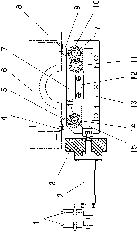
[0009] Such as figure 1 As shown: the device includes a bracket 3 and a support plate 7 fixed on the clamp body of the machine tool, an oil cylinder 2 connected with a hydraulic control device is fixedly connected to the bracket 3, and a rack 15 is slidably installed on the support plate 7, specifically The installation method is that the support plate 7 is provided with a guide plate 12 fixed by bolts, and the top of the rack 15 is located between the support plate 7 and the guide plate 12 . On the support plate 7, a side baffle 13 is fixed by bolts, and the lower part of the rack 15 is located between the support plate 7 and the side baffle 13, so that the tooth bar 15 can slide freely relative to the support plate 7.
[0010] The end of the piston rod matched with the oil cylinder 2 is connected to one end of the rack 15 through a connecting screw, and the left shaft 16 is connected to the support plate 7 through a bearing sleeve, and a left gear meshing with the rack 15 is...
PUM
 Abstract
Description
Claims
Application Information
 - Generate Ideas
- Intellectual Property
- Life Sciences
- Materials
- Tech Scout
- Unparalleled Data Quality
- Higher Quality Content
- 60% Fewer Hallucinations
Browse by: Latest US Patents, China's latest patents, Technical Efficacy Thesaurus, Application Domain, Technology Topic, Popular Technical Reports.
© 2025 PatSnap. All rights reserved.Legal|Privacy policy|Modern Slavery Act Transparency Statement|Sitemap|About US| Contact US: help@patsnap.com