Automatic wax injection machine for producing wax sticks

A technology of wax injection machine and wax rod, which is applied in the direction of casting and molding equipment, etc., can solve the problems of high labor intensity, low production efficiency, and easy to cause work-related accidents, and achieve the effect of reducing labor intensity, improving production efficiency and reducing work-related accidents

Inactive Publication Date: 2014-03-12
郏银芳
View PDF4 Cites 6 Cited by
  • Summary
  • Abstract
  • Description
  • Claims
  • Application Information

AI Technical Summary

Problems solved by technology

[0002] At present, the following methods are usually used in the industry to produce wax sticks: firstly, the mold is closed manually and fixed with bolts. After the mold is closed, a cavity for molding the wax stick is formed, and then wax is poured into the cavity. Then insert one end of the wax stick handle into the wax slurry and ensure that the wax stick handle is in the center of the cavity. Hold the wax stick handle until the wax slurry is kept under pressure and cooled before it can be released. Disassemble the mold and take it out for molding Finally, put the wax stick together with the handle of the wax stick into the water tank for cooling, so as to complete the production of a wax stick. From the above content, we can easily see that each process of producing wax sticks requires manual operation. , if it is produced in batches, the production workers will continue to repeat the above work. Obviously, this is not only low in production efficiency and high in labor intensity, but also in the disassembly and assembly of heavy molds.

Method used


Image

  • Automatic wax injection machine for producing wax sticks
  • Automatic wax injection machine for producing wax sticks
  • Automatic wax injection machine for producing wax sticks

Examples


Embodiment Construction

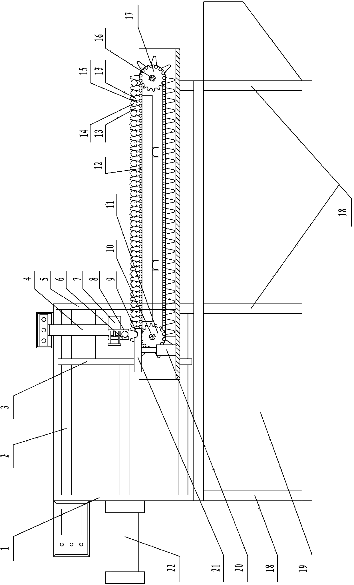
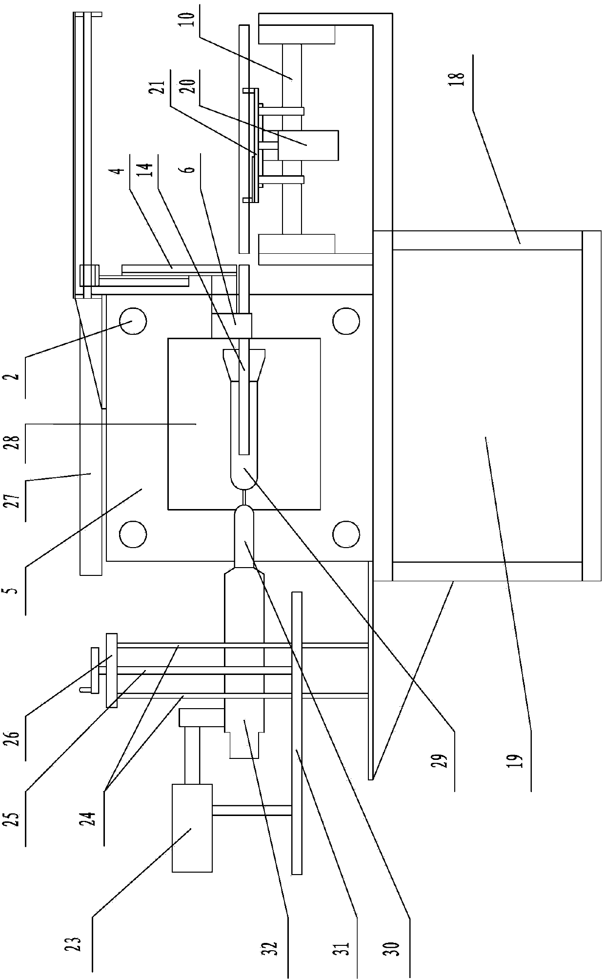
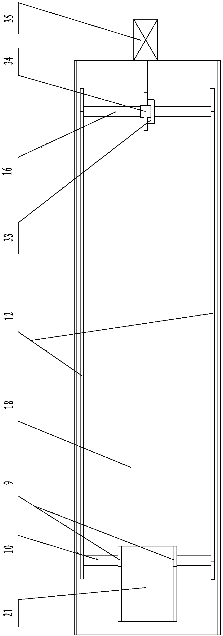
[0014] Below in conjunction with accompanying drawing and specific embodiment, the automatic wax injecting machine that the present invention is used to produce wax stick is described in further detail:

[0015] Such as figure 1 and figure 2 As shown, in this specific embodiment, the automatic wax injection machine for producing wax sticks of the present invention includes a frame 18, a first fixed plate 1, a second fixed plate 5, and an arrangement conveying device for transporting wax stick handles 14 , a lifting device for lifting the wax stick handle 14, a feeding device for sending one end of the wax stick handle 14 into the mold cavity 29 and a wax injection device for injecting the wax slurry into the mold cavity 29, injecting Wax device, lifting device and arrangement conveying device are all contained on the frame 18, and feeding device is contained in the second fixed plate 5 tops and is positioned at the lifting device top, and lifting device is positioned at the ...


PUM


Abstract

The invention discloses an automatic wax injection machine for producing wax sticks. The automatic wax injection machine comprises a rack, a first fixed plate, a second fixed plate, an arranging and conveying device for conveying wax stick stems, a lifting device for lifting the wax stick stems, a feeding device for feeding the wax stick stems into a mold cavity, and a wax injection device for injecting wax slurry into the mold cavity, wherein the wax injection device, the lifting device and the arranging and conveying device are all arranged on the rack; the feeding deice is arrange on the top of the second fixed plate and is positioned above the lifting device; the lifting device is positioned on the left side of the arranging and conveying device; both the first fixed plate and the second fixed plate are connected with the rack; a guide column is arranged between the first fixed plate and the second fixed plate and is connected with a movable plate in a sliding manner; the first fixed plate is connected with a pressing cylinder for driving the movable plate to slide; a cooling water tank is arranged on the rack and is positioned below the first fixed plate, the movable plate and the second fixed plate. According to the automatic wax injection machine, the production efficiency can be greatly improved, the labor intensity is reduced, and the personal safety of production workers can be guaranteed.

Description

Technical field: [0001] The invention relates to automatic mechanical equipment in the precision casting industry, in particular to an automatic wax injection machine for producing wax sticks. Background technique: [0002] At present, the following methods are usually used in the industry to produce wax sticks: firstly, the mold is closed manually and fixed with bolts. After the mold is closed, a cavity for molding the wax stick is formed, and then wax is poured into the cavity. Then insert one end of the wax stick handle into the wax slurry and ensure that the wax stick handle is in the center of the cavity. Hold the wax stick handle until the wax slurry is kept under pressure and cooled before it can be released. Disassemble the mold and take out the molding Finally, put the wax stick together with the handle of the wax stick into the water tank for cooling, so as to complete the production of a wax stick. From the above content, we can easily see that each process of pro...

Claims


Application Information

Patent Timeline
Patent Type & Authority Applications(China)
IPC IPC(8): B29C45/14B29C45/03B29C31/08
CPCB22C7/02
Inventor 郏银芳郏宇乐
Owner 郏银芳
Why Eureka
Try Eureka