A self-adjusting deceleration belt with vehicle speed recognition

An automatic adjustment and deceleration belt technology, which is applied in the direction of roads, road signs, traffic signals, etc., can solve the problems of reducing the vibration of low-speed vehicles, the spring bears a lot, and the spring requirements are too high, so as to slow down the rapid deformation and increase the deceleration effect , Increase the effect of vehicle weight range

Active Publication Date: 2016-08-17
泰州市海通资产管理有限公司
View PDF5 Cites 0 Cited by
  • Summary
  • Abstract
  • Description
  • Claims
  • Application Information

AI Technical Summary

Problems solved by technology

However, this design has too high requirements on the spring. The spring bears a lot of pressure when the deceleration belt is pressed down. When the deceleration belt rises and returns to its original position, the liquid on the upper part of the piston plate completely relies on the spring to release the elastic potential energy and presses back to the lower part. It is known that the process of liquid passing through the permeable hole is slow, requiring the spring to continuously and strongly squeeze the liquid
The hydraulic device can indeed slow down the descent speed during the descent of the speed bump, but its structure also prevents the speed bump from being reset in time, and the slow ascent process may cause the speed bump to be unable to exert any binding force on the following vehicles
At the same time, the existing hydraulic speed bumps have high requirements on the airtightness of the hydraulic device, making it difficult to realize
Existing speed bumps do not have the ability to distinguish the speed of driving vehicles, and cannot reduce the vibration of low-speed vehicles while maintaining punitive vibrations for high-speed vehicles

Method used


Image

  • A self-adjusting deceleration belt with vehicle speed recognition
  • A self-adjusting deceleration belt with vehicle speed recognition
  • A self-adjusting deceleration belt with vehicle speed recognition

Examples


Embodiment Construction

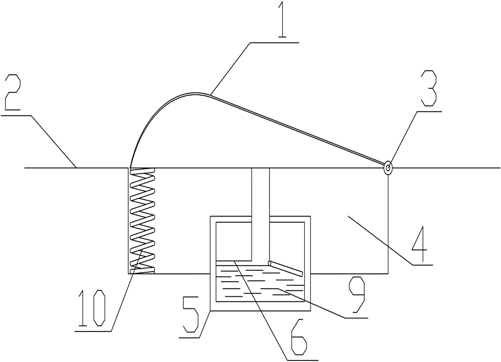
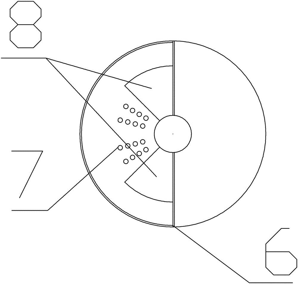
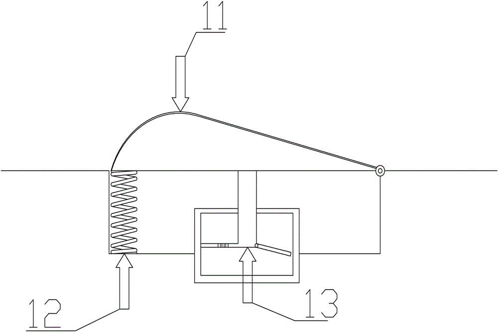
[0022] As shown in Figures 1 and 2, an automatic speed reduction belt with recognized vehicle speed includes a speed reduction belt panel 1, a sticky cylinder 5, and a piston plate 6; one end of the speed reduction belt panel 1 is fixed on the ground 2 through a shaft 3, and the other end is passed through The elastic part is in contact with the bottom surface of the concave 4 of the ground 2, the elastic part is a spring 10, a connecting rod is fixed on the speed bump panel 1, the cross section of the speed bump panel 1 is a parabolic turning line, and the non-fixed end of the connecting rod is provided with a piston Plate 6, the piston plate 6 is provided with a permeable hole 7, and the piston plate 6 is movable and fixed with a permeable hole adjustment plate 8, which can cover the permeable hole 7 by rotating the permeable hole adjustment plate 8; the sticky cylinder 5 is fixed in the groove on the ground, sticking Liquid 9 is installed in the cylinder 5, and the piston pl...


PUM


Abstract

An automatically adjustable speed bump with vehicle speed recognition, including a speed bump panel, a sticky cylinder, and a piston plate; one end of the speed bump panel is movably fixed on the ground, and the other end is in contact with the ground through elastic components, and a connecting rod is fixed on the speed bump panel , the non-fixed end of the connecting rod is provided with a piston plate, and the piston plate is provided with a permeable hole; the sticky cylinder is fixed in the groove on the ground, the sticky cylinder is filled with liquid, and the piston plate can be set in the sticky cylinder as a vertical Movement, the liquid can only overflow or return to the viscous cylinder through the permeable hole. The present invention has the advantage that it can distinguish the speed of the vehicle to regulate its own blocking strength, and can self-adjust to adapt to the speed bump in different traffic environments.

Description

technical field [0001] The invention designs traffic safety facilities, relates to the field of new special facilities for traffic safety, and in particular relates to an automatic speed reduction belt with the ability to recognize vehicle speed. Background technique [0002] Judging from the effect of speed bumps in recent years, speed bumps are a double-edged sword. Speed ​​bumps can effectively improve road traffic safety conditions, on the contrary, they may have little effect or even become artificial roadblocks on the road. Most of the current speed bumps make the road surface arched to achieve the purpose of vehicle deceleration. However, when the vehicle passes the speed bump, there will be violent vibration without exception, and the feeling of discomfort and insecurity will arise spontaneously. [0003] There is already a noise reduction hydraulic speed bump device design in China. The purpose of using hydraulic design is to reduce the noise pollution generated wh...

Claims


Application Information

Patent Timeline
Patent Type & Authority Patents(China)
IPC IPC(8): E01F9/529
Inventor 刘杰夏骏李建林胡静蔡健肖蕾唐亮汤天彩范留军郭金龙
Owner 泰州市海通资产管理有限公司
Why Eureka
Try Eureka