Optical module testing device

A technology for optical module testing and testing status, applied in the direction of measuring device, measuring device casing, electronic circuit testing, etc., can solve the problems of poor accuracy, low testing accuracy, affecting testing accuracy and efficiency, etc. The effect of stable installation and connection and simple structure

Active Publication Date: 2014-03-12
SOURCE PHOTONICS CHENGDU
View PDF9 Cites 9 Cited by
  • Summary
  • Abstract
  • Description
  • Claims
  • Application Information

AI Technical Summary

Problems solved by technology

[0004] Existing test tooling usually uses welding to weld the flexible circuit board on the test platform for testing. As the circuit distribution on the flexible circuit board is getting denser and the test points are getting smaller and smaller, the existing The traditional probe test method is slow, difficult to test repeatedly, and the test accuracy is low and the precision is poor, especially reflected in the difficulty of controlling and adjusting the test pressure, which seriously affects the accuracy and efficiency of the test

Method used


Image

  • Optical module testing device
  • Optical module testing device
  • Optical module testing device

Examples


Embodiment Construction

[0024] The present invention will be further described in detail below in conjunction with test examples and specific embodiments. However, it should not be understood that the scope of the above subject matter of the present invention is limited to the following embodiments, and all technologies realized based on the content of the present invention belong to the scope of the present invention.

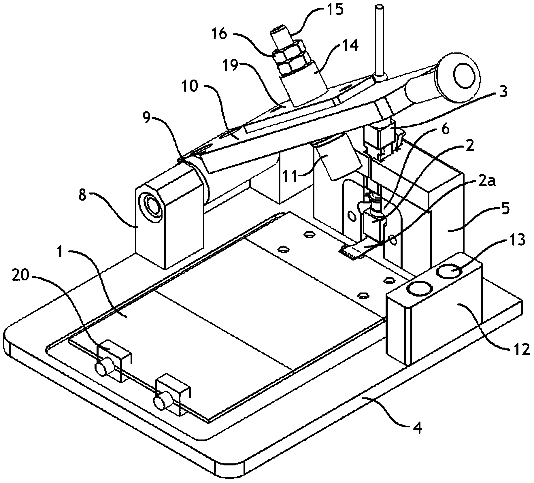
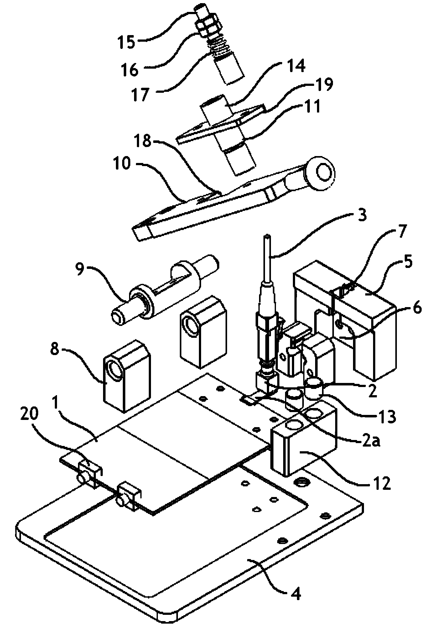
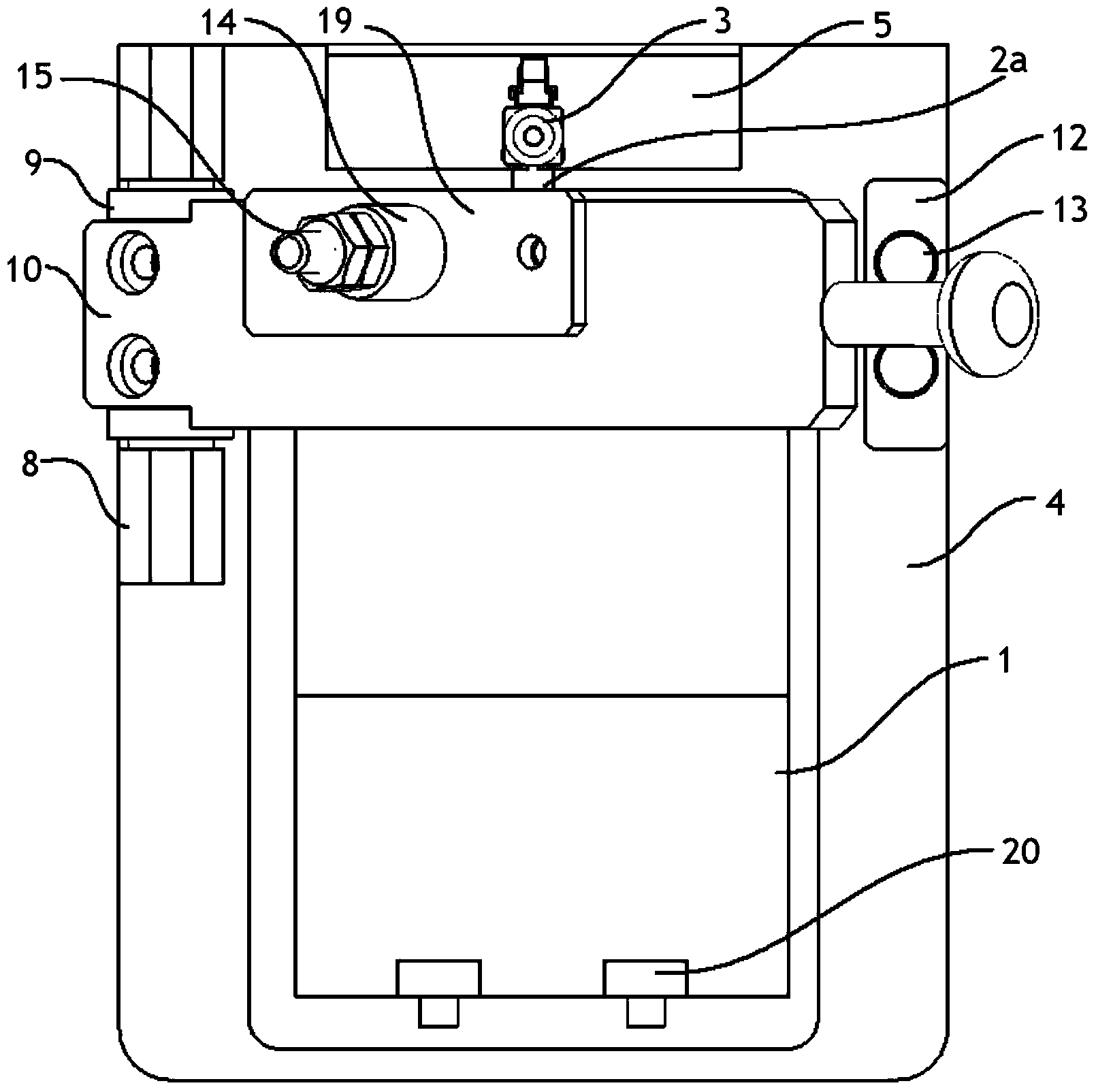
[0025] like Figure 1 to Figure 5 As shown, the present embodiment is a kind of optical module testing device, comprises PCB board 1, optical module to be tested 2 and optical fiber jumper 3, is provided with flexible circuit board 2a on the optical module to be tested 2, under test state, optical fiber jumper 3 is connected to the optical module 2 to be tested, the flexible circuit board 2a of the optical module 2 to be tested is electrically connected to the PCB board 1, the PCB board 1 is arranged on the bottom board 4, and the bottom board 4 is provided with a jumper socket 5, an...


PUM


Abstract

The invention discloses an optical module testing device which comprises a PCB (printed circuit board), a to-be-tested optical module and an optical fiber patch cord. A flexible circuit board is disposed on the to-be-tested optical module. In a testing state, the optical fiber patch cord is connected with the to-be-tested optical module, the flexible circuit board of the to-be-tested optical module is electrically connected with the PCB which is disposed on a bottom plate, a patch cord inserting seat is disposed on the bottom plate, a module mounting hole is formed between the patch cord inserting seat and the bottom plate, a patch cord inserting hole is formed above the module mounting hole, and when the optical fiber patch core is inserted into the patch core inserting hole, the optical fiber patch core is electrically connected with the to-be-tested optical module disposed in the module mounting hole. The optical module testing device has the advantages that a pressure head is connected through a rotary shaft and a pressing plate, the testing device is simple in structure and good in structural stability during testing, mounting and demounting of each part are convenient, and repeated testing by using different PCBs, different to-be-tested modules, and the like is facilitated.

Description

technical field [0001] The invention relates to the field of FPC testing of flexible circuit boards, in particular to an optical module testing device. Background technique [0002] Flexible printed circuit board (Flexible Printed Circuit Board), also known as "soft board", is a printed circuit made of flexible insulating substrates. It has many advantages that rigid printed circuit boards do not have, such as it can be bent, wound, and folded freely. , can be arranged arbitrarily according to the spatial layout requirements, and can be moved and expanded arbitrarily in three-dimensional space, so as to achieve the integration of component assembly and wire connection. [0003] After the flexible circuit board is produced, it is necessary to test the corresponding points, and judge whether the flexible circuit board is good or bad by the size of the resistance. parameters to test. [0004] Existing test tooling usually uses welding to weld the flexible circuit board on the...

Claims


Application Information

Patent Timeline
Patent Type & Authority Applications(China)
IPC IPC(8): G01R31/00G01R31/28G01R1/04
Inventor 张绍友王自力王洪宾
Owner SOURCE PHOTONICS CHENGDU
Why Eureka
Try Eureka