
Antenna array SAR polar coordinate overlapped sub-aperture imaging method

A technology of overlapping sub-apertures and imaging methods, which is applied in radio wave measurement systems, radio wave reflection/re-radiation, and re-radiation, can solve problems such as inability to compensate for wavefront bending errors, and achieve high-precision imaging processing, The effect of low memory usage and small amount of calculation

Active Publication Date: 2014-03-12
INST OF ELECTRONICS CHINESE ACAD OF SCI
View PDF0 Cites 13 Cited by
  • Summary
  • Abstract
  • Description
  • Claims
  • Application Information

AI Technical Summary

Problems solved by technology

[0003] However, the applicant found that the above-mentioned array SAR polar coordinate imaging method performs Fraunhofer approximation on the distance history, which cannot compensate the wavefront bending error, and the imaging accuracy is greatly affected by the wavefront bending, especially when the imaging scene is large and the surveying distance is relatively large. In the near case, the effect of wave front bending is more obvious

Method used


Image

  • Antenna array SAR polar coordinate overlapped sub-aperture imaging method
  • Antenna array SAR polar coordinate overlapped sub-aperture imaging method
  • Antenna array SAR polar coordinate overlapped sub-aperture imaging method

Examples


Embodiment Construction

[0022] In order to make the objectives, technical solutions, and advantages of the present invention clearer, the following further describes the present invention in detail in conjunction with specific embodiments and with reference to the accompanying drawings. It should be noted that in the drawings or description of the specification, similar or identical parts use the same drawing numbers. The implementations not shown or described in the drawings are those known to those of ordinary skill in the art. In addition, although this article may provide an example of a parameter containing a specific value, it should be understood that the parameter does not need to be exactly equal to the corresponding value, but can be approximated to the corresponding value within an acceptable error tolerance or design constraint.

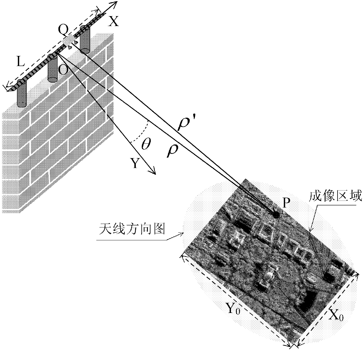
[0023] The invention provides an array antenna SAR polar coordinate overlapping sub-aperture imaging method. This method is proposed for array antenna SAR imaging...


PUM


Abstract

The invention provides an antenna array SAR polar coordinate overlapped sub-aperture imaging method for a two-dimension SAR imaging system consisting of array antennas. The method is suitable for an array antenna radar system of which the transmitting signal is a Chirp signal or an SFCW signal. The method comprises the steps of completing range frequency matched filtering, carrying out Polar Formatting transform to represent an observation scene object in a polar coordinate system, completing range imaging through range Fourier transform, and then completing high-precision wave-front curvature compensation and azimuth imaging processing through overlapped sub-aperture processing in the azimuth direction so as to obtain a high-precision two-dimension image.

Description

Technical field [0001] The invention relates to the technical field of radar imaging and signal processing, in particular to an array antenna SAR polar coordinate overlapping subaperture imaging method. Background technique [0002] In conventional SAR imaging systems, to achieve high resolution in azimuth, the system PRF needs to be improved, but the improvement of PRF brings great challenges to the system implementation. Array SAR imaging system uses physical arrays to achieve rapid switching between array elements instead of platform movement to form a synthetic aperture, which can reduce system PRF requirements. The array SAR imaging system has very broad application prospects in moving target detection and high-resolution imaging systems. The current imaging methods of the array antenna SAR imaging system mainly include the ω-k algorithm, the backward projection algorithm, etc. In the process of implementing the present invention, the applicant found that the above-mentione...

Claims


Application Information

Patent Timeline
Patent Type & Authority Applications(China)
IPC IPC(8): G01S13/90G01S7/41
CPCG01S13/90G01S13/9011
Inventor 王彦平彭学明洪文吴一戎谭维贤
Owner INST OF ELECTRONICS CHINESE ACAD OF SCI
Learn More