Eureka AIR delivers breakthrough ideas for toughest innovation challenges, trusted by R&D personnel around the world.

Computer and control method for smart fan thereof

A control method and intelligent technology, applied in auxiliary non-electrical temperature control, calculation, energy-saving calculation, etc., can solve problems such as difficulty for users to monitor the operation of intelligent fans, difficulty for users, and inability to effectively control the speed of intelligent fans.

Active Publication Date: 2014-03-12
MSI ELECTRONICS KUN SHAN
View PDF5 Cites 12 Cited by
  • Summary
  • Abstract
  • Description
  • Claims
  • Application Information

AI Technical Summary

Problems solved by technology

[0004] However, when controlling the fan under the traditional Basic Input Output System (BIOS), only the currently sensed temperature and the fan speed are displayed in a textual manner, which cannot allow users to quickly understand the current smart devices. Efficiency of fan operation and internals of computer equipment
When the number of smart fans increases, it becomes more difficult for users to monitor the operation of each smart fan
As a result, it is also difficult to properly adjust the speed of the smart fan according to the site environment
[0005] In other words, the current technology for controlling smart fans in BIOS mode has a lackluster information display method, which makes it difficult for users to understand the operation status of smart fans and the heat dissipation of computer devices, and thus cannot effectively control the speed of smart fans.

Method used


Image

  • Computer and control method for smart fan thereof
  • Computer and control method for smart fan thereof
  • Computer and control method for smart fan thereof

Examples


Embodiment Construction

[0049] The detailed features and advantages of the present invention are described in detail in the following embodiments, and the content is sufficient for those skilled in the art to understand the technical content of the present invention and implement it accordingly, and according to the content disclosed in this specification, claims and drawings, Those skilled in the art can easily understand the related objects and advantages of the present invention.

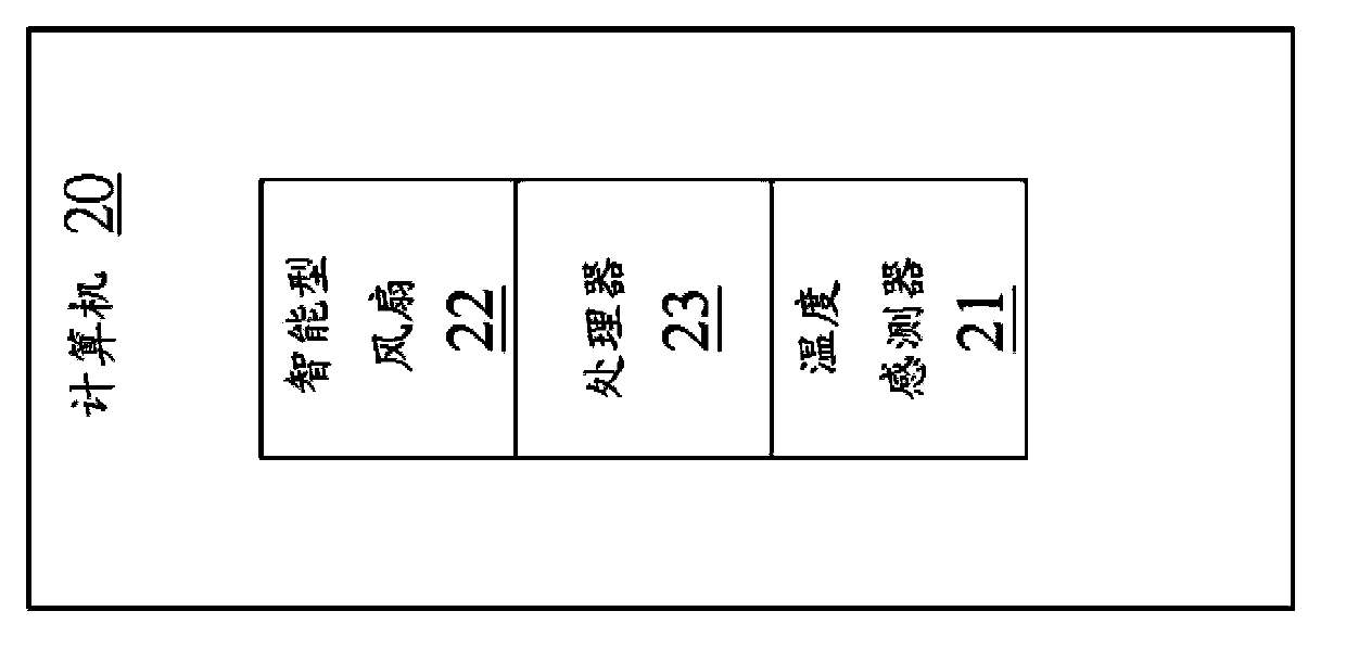
[0050] The present invention provides a computer and a control method of an intelligent fan, and the control method of the intelligent fan is used to control a computer in a Unified Extensible Firmware Interface Basic Input Output System (UEFI BIOS) mode At least one smart fan of the computer. Among them, UEFI BIOS is a higher-level BIOS. Compared with traditional BIOS, UEFI BIOS can provide more diversified display and control methods.

[0051] The computer includes at least one smart fan, at least one temperature sensor, ...


PUM


Abstract

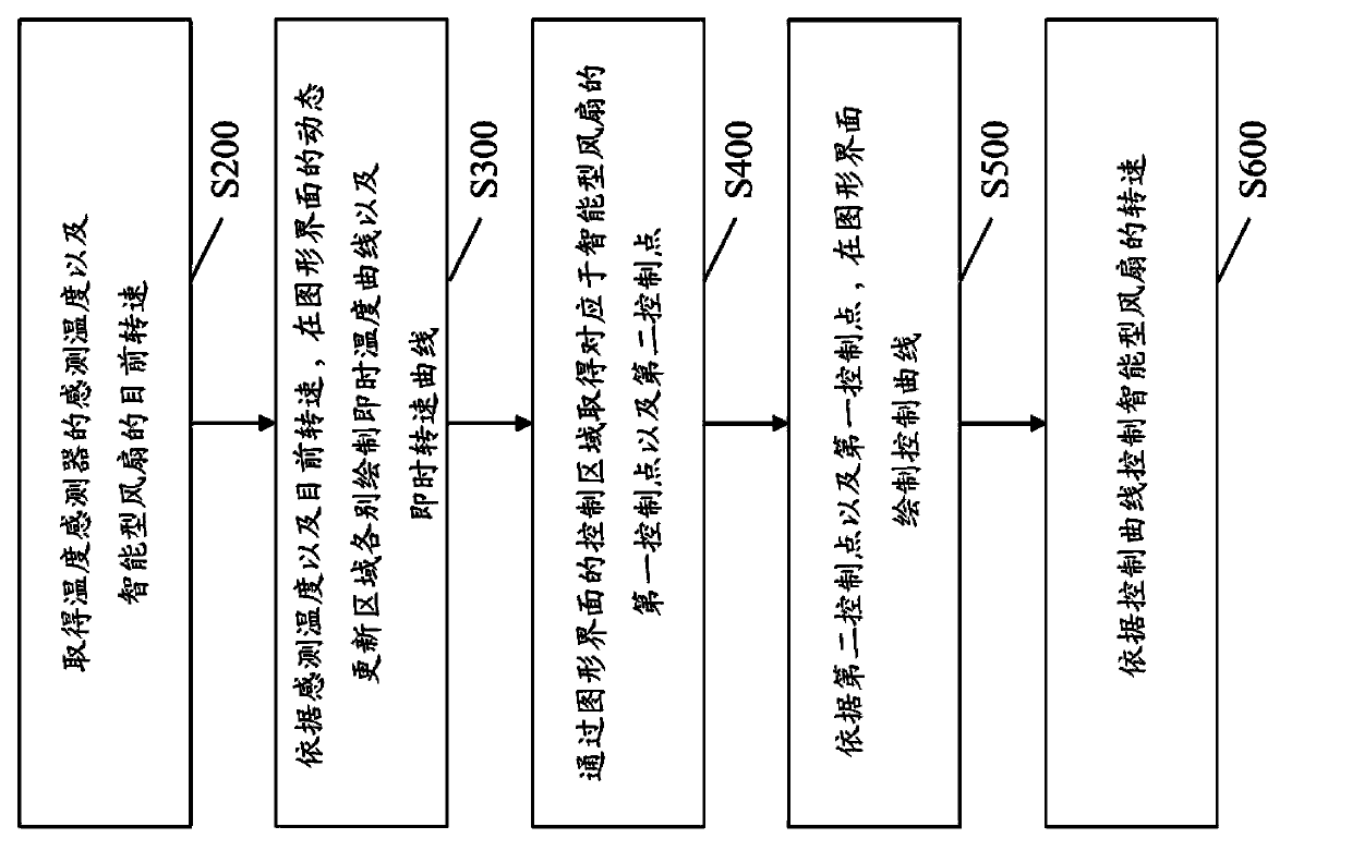
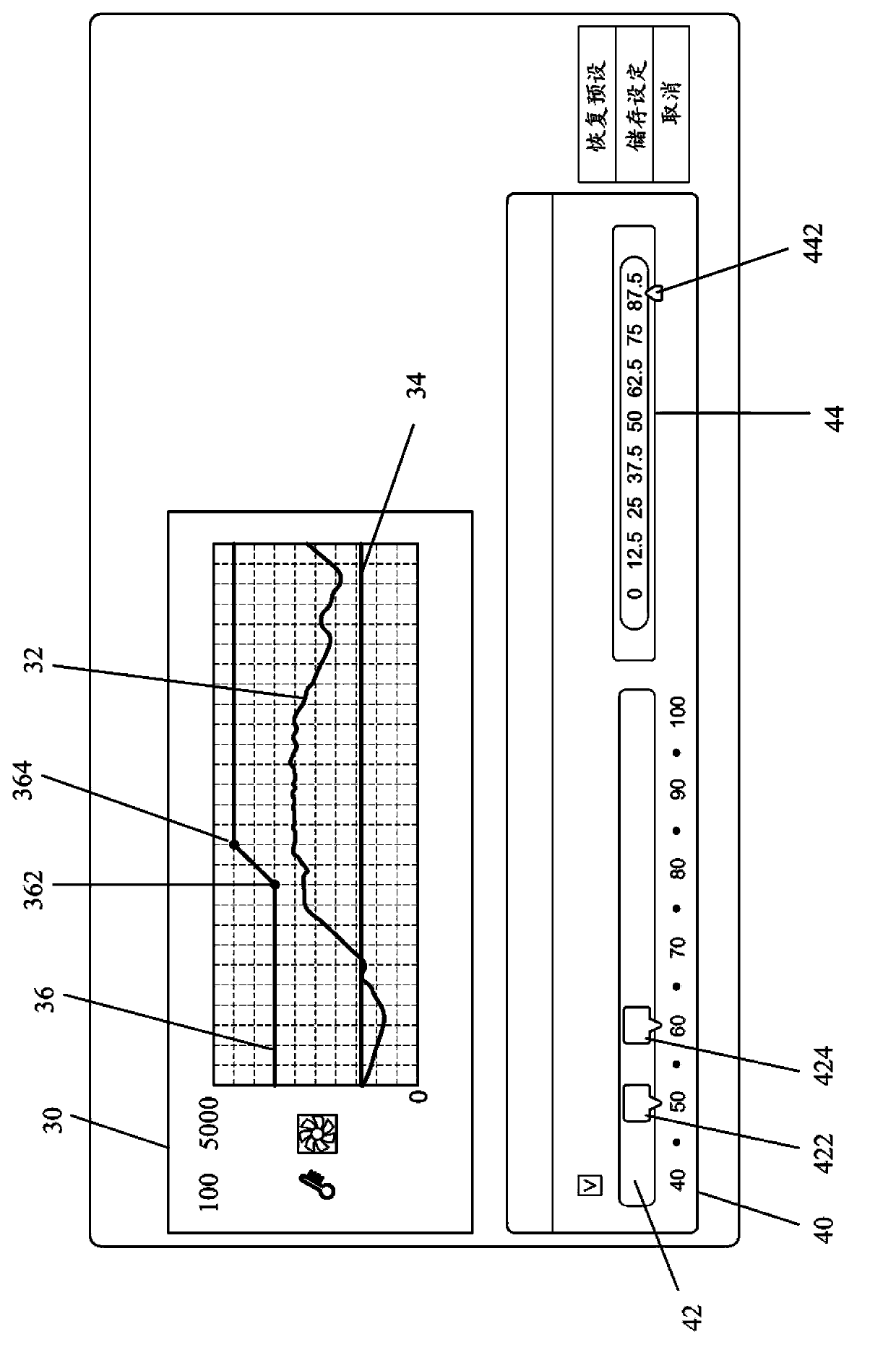
A computer and a control method for smart fan thereof are provided, wherein the computer includes a processor configured to control a smart fan under an UETFI bios mode. A sensed temperature value from a temperature sensor, and a current speed value of the smart fan are acquired. A real-time temperature curve and a real-time speed curve are traced in a dynamic updating zone of a graphical interface respectively according to the current temperature and the current speed value. A first control point and a second control point, which correspond to the smart fan, are obtained via a control zone of the graphical interface. A control curve is traced in the graphical interface according to the first and second control points. The speed of the smart fan is controlled according to the control curve. And therefore the user can set the control points according to the temperature curve and the rotating speed curve.

Description

Technical field [0001] The invention relates to a computer and a fan control method thereof, in particular to a computer with an intelligent fan and a control method of the intelligent fan. Background technique [0002] With the advancement of manufacturing technology, more and more electronic components are configured in various computer devices, and the configuration methods are more complicated. In addition, the design of the computer device is based on the consideration of being as thin as possible, so the internal components are arranged quite closely. The electronic components generate a lot of heat when they are in use, making the heat dissipation mechanism of the computer device a very important part of the device design. [0003] For heat dissipation issues, the general focus is on fan speed control and noise; the higher the fan speed, the louder the noise. Most traditional fans can only maintain a fixed speed after starting. In order to improve heat dissipation efficien...

Claims


Application Information

Patent Timeline
Patent Type & Authority Applications(China)
IPC IPC(8): G06F1/20
CPCH05K7/20209Y02B60/1275G06F3/0484G05D23/185G06F1/20G06F1/206H05K7/20836G06F3/04817G06F1/203Y02D10/00
Inventor 陈重位吴伟诚
Owner MSI ELECTRONICS KUN SHAN
Why Eureka
Eureka Blog
Learn More