An output voltage control method and circuit of an isolated ac-dc power supply

An output voltage control and output voltage technology, applied in control/regulation systems, output power conversion devices, conversion of DC power input to DC power output, etc., to simplify system layout and wiring, save transformer and system costs, and improve system signals. The effect of utilization

Active Publication Date: 2015-12-09
QX MICRO DEVICES
View PDF4 Cites 1 Cited by
  • Summary
  • Abstract
  • Description
  • Claims
  • Application Information

AI Technical Summary

Problems solved by technology

[0008] The disadvantage of the traditional technology is that the transformer of the system must have an auxiliary winding, and the switching action of the power switch tube must be used to sample the output voltage during the demagnetization time of the transformer.

Method used


Image

  • An output voltage control method and circuit of an isolated ac-dc power supply
  • An output voltage control method and circuit of an isolated ac-dc power supply
  • An output voltage control method and circuit of an isolated ac-dc power supply

Examples


no. 1 example

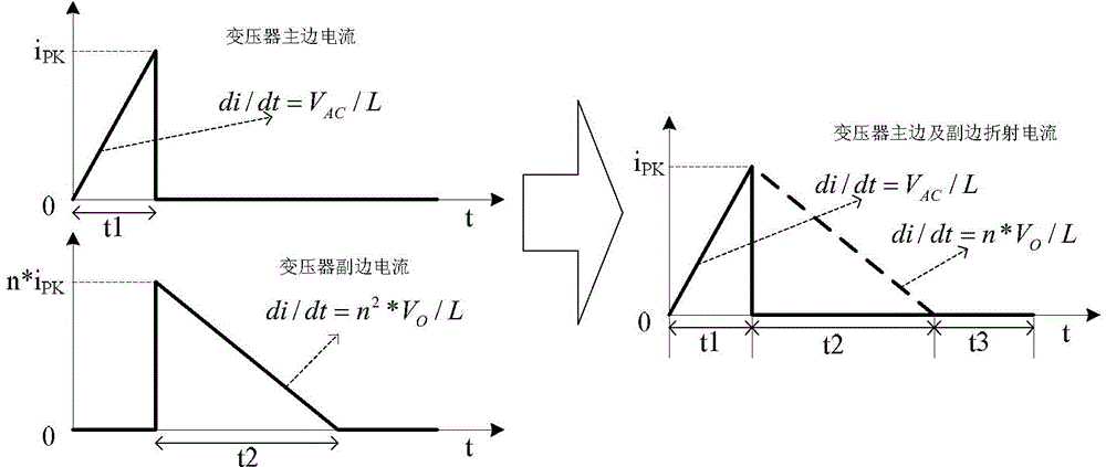
[0053] like Figure 4-5 , if the chip U2 works normally, it can accurately detect the conduction time t1 and demagnetization time t2 of the transformer, and adjust the voltage of the COMP1 pin at the same time, so that the chip

[0054] V FB 1 * t 1 t 2 = V REF 1 - - - ( 7 )

[0055] where V FB1 It is the resistor divider of the chip VFB1 pin voltage, that is, the input line voltage.

[0056] Then from the formula (6) we can get

[0057] V O = V AC n * t 1 t ...

no. 2 example

[0068] Another specific embodiment of the present invention is Figure 7 As shown, a specific implementation method of the output voltage evaluation unit is Figure 8 middle circuit.

[0069] from Image 6 and Figure 7 It can be seen that when the switch S1 is turned on, that is, during the time period t1, the current on the resistor R5

[0070] I R5 =V AC / R5=I FB2 (12)

[0071] During the time period t2, the current on the resistor R6

[0072] I R6 =V REF2 / R6=I REF2 (13)

[0073] Similarly, when the chip U3 is stable, the voltage on the output COMP2 is stable, and the charging charge on the capacitor C1 is equal to the discharging charge

[0074] I REF2 *t2=I FB2 *t1(14)

[0075] Substituting formula (12) into formula (6), we can get

[0076] V O = V AC n * t 1 t ...


PUM


Abstract

The invention relates to a method and circuit for controlling output voltage of an isolated AC-DC (Alternating Current-Direct Current) power supply. The circuit can use a two-winding transformer (T2), wherein a PWM (Pulse Width Modulation) control chip (U2) in the circuit comprises an output voltage evaluation unit, a current comparison and logic control unit and a demagnetizing time detection unit, wherein the output voltage evaluation unit and the current comparison and logic control unit are electrically connected sequentially from input to output, and the demagnetizing time detection unit is located between the output voltage evaluation unit and an output terminal of the PWM control chip (U2) and is used for detecting the conducting time t1 and demagnetizing time t2 of the transformer. The method comprises the step of enabling V0 to reach a set value by using the relationship (represented by an equation shown in a drawing) among the output voltage V0 of the transformer, VAC, t1, t2 and the turns ratio n of the transformer. The method and the circuit have the advantages that the cost of a system is reduced, and the layout and wiring of the system are simplified.

Description

technical field [0001] The invention relates to an electronic circuit and signal processing technology, in particular to an output voltage control method and a circuit of an isolated alternating current to direct current (AC-DC) power supply. Background technique [0002] With the application of AC / DC switching power supply systems more and more widely, isolated power supplies are favored by customers because of their high safety performance due to the isolation of output and input line voltage. According to the type of system feedback, AC / DC switching power supply can be divided into primary side feedback (PSR) type and secondary side feedback type. Among them, the primary side feedback type saves the system cost and simplifies the system design because the external components such as optocoupler and TL431 required by the secondary side feedback type are omitted. [0003] The traditional primary side feedback type flyback control system, the circuit block diagram is as fol...

Claims


Application Information

Patent Timeline
Patent Type & Authority Patents(China)
IPC IPC(8): H02M3/335
Inventor 李剑黄朝刚
Owner QX MICRO DEVICES
Why Eureka
Try Eureka