Optical modulation system and method thereof

A light modulation and light source technology, applied in the transmission system, electromagnetic wave transmission system, electrical components, etc., can solve the problems of high driving voltage, difficult integration, polarization sensitivity, etc., and achieve the effect of low cost and small size

Active Publication Date: 2014-03-12
BEIJING UNIV OF POSTS & TELECOMM
View PDF8 Cites 6 Cited by
  • Summary
  • Abstract
  • Description
  • Claims
  • Application Information

AI Technical Summary

Problems solved by technology

The modulator usually has a relatively high driving voltage, is sensitive to polarization, and is difficult to integrate with optical devices such as light sources

Method used


Image

  • Optical modulation system and method thereof
  • Optical modulation system and method thereof
  • Optical modulation system and method thereof

Examples


Embodiment Construction

[0039] The specific implementation manners of the present invention will be further described in detail below in conjunction with the accompanying drawings and embodiments. The following examples are used to illustrate the present invention, but are not intended to limit the scope of the present invention.

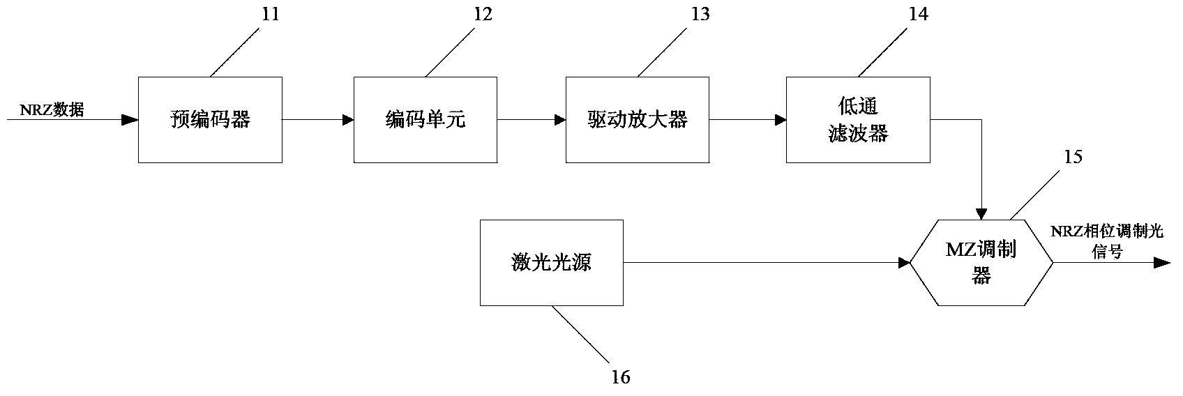
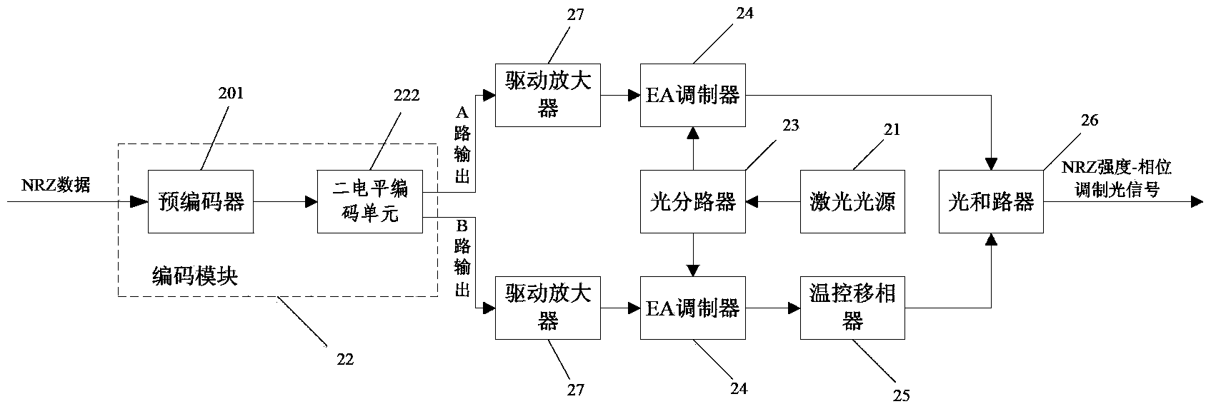
[0040] Such as figure 2 As shown, the light modulation system includes: a light source, and

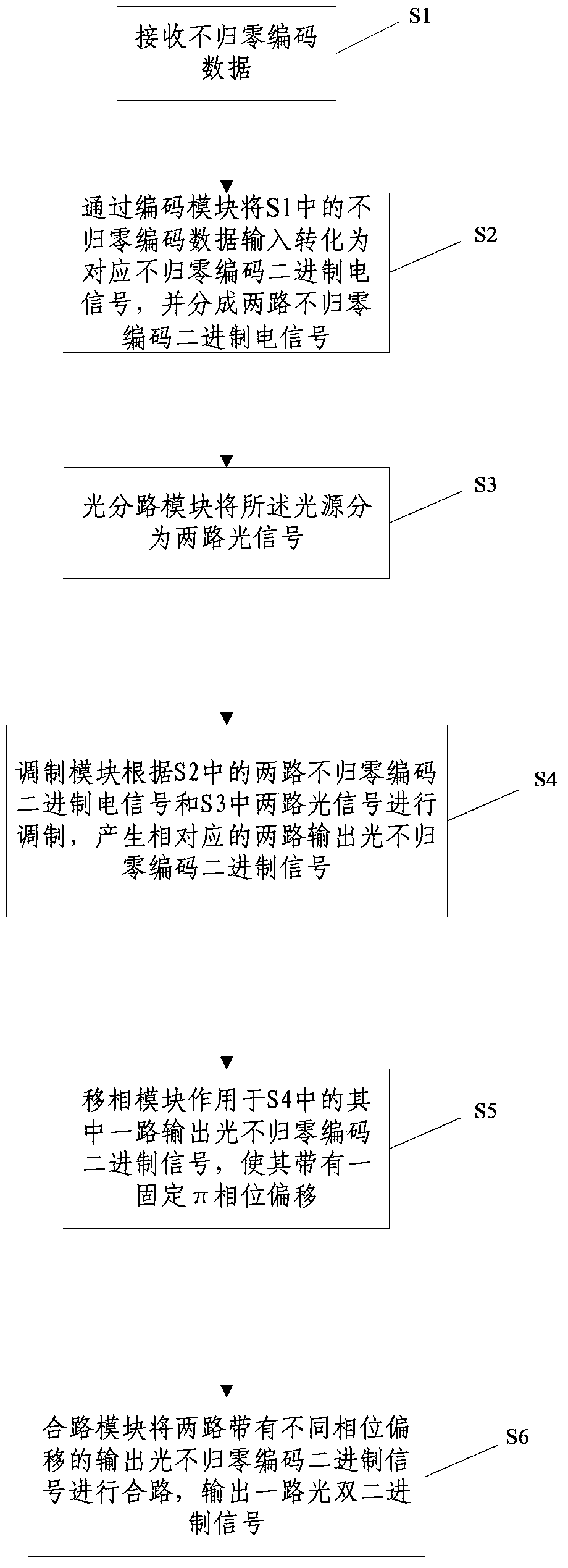
[0041] Coding module 22: controlling and connecting to the modulation module, used to transform the non-return-to-zero coded data input into the required two-way intensity modulation driving electrical signals;

[0042] Optical branching module: its input terminal is connected to the light source, and its output terminal is connected to the modulation module, which is used to branch the light source into at least two paths;

[0043] Modulation module: its input end is connected to the optical branching module, and its output end is connected to the phase shifting module, which ...


PUM


Abstract

The invention discloses an optical modulation system and a method thereof, the system comprising an optical source; a coding module for controlling and connecting to a modulation module; an optical splitting module, an input terminal of which is connected to the optical source and an output terminal of which is connected to the modulation module; the modulation module, an input terminal of which is connected to the optical splitting module and an output terminal of which is connected to a phase-shift module; the phase-shift module, an input terminal of which is connected to the modulation module and an output terminal of which is connected to an optical combining module; and the optical combining module, an input terminal of which is connected to the phase-shift module and an output terminal of which is connected to an optical transmission line. The optical modulation system and the method thereof achieve single-stage intensity modulation by modulating an EA modulator after an electric field is converted into a two-level NRZ signal, and an optical duobinary modulation signal with different phase information may be formed by combination with a phase shifter. Further, compared with a modulation system and a method thereof which use a single-stage MZ modulator for optical duobinary modulation, the optical modulation system and the method thereof are more integrated in product structure, smaller in product size and lower in cost.

Description

technical field [0001] The invention relates to the technical field of optical fiber communication, in particular to an optical modulation system and its method, in particular to an optical binary code pattern modulation system and its method. Background technique [0002] With the continuous improvement of the data rate of the optical communication system and the widespread use of EDFA, the dispersion becomes an important factor restricting the transmission distance. A narrow-band, high-dispersion-tolerant format is sought to replace the traditional binary transmission format. [0003] Non-return to zero coding (Not Return to Zero, NRZ), the traditional binary transmission format is generally binary NRZ format, when the signal of this modulation format is transmitted in the optical fiber medium, due to the DC frequency component of the signal and the high frequency that occurs during the modulation process The expansion of components will stimulate nonlinearity and dispers...

Claims


Application Information

Patent Timeline
Patent Type & Authority Applications(China)
IPC IPC(8): H04B10/516
Inventor 陈雪石玥刘岩王立芊张治国
Owner BEIJING UNIV OF POSTS & TELECOMM
Why Eureka
Try Eureka