Fluidized bed reactor
A technology of fluidized bed reactor and straight cylinder, which is applied in the field of reactors and can solve the problems of weak market competitiveness and few brands
- Summary
- Abstract
- Description
- Claims
- Application Information
AI Technical Summary
Problems solved by technology
Method used
Image

Examples
Embodiment 1
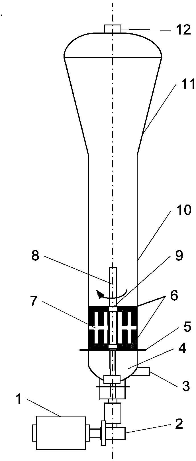
[0034] like figure 1 As shown, the fluidized bed of the present invention is followed by a gas-gathering section 4, a straight cylinder section 10 and an enlarged section 11 from bottom to top, a gas distribution plate 5 is installed between the gas-gathering section 4 and the straight cylinder section 10, and a gas distribution plate 5 is arranged at the bottom of the gas-gathering section 4. There is a circulating gas inlet 3.
[0035] The power mechanism composed of motor 1 and reducer 2 is installed outside the fluidized bed. The output end of the reducer 2 is connected to the rotating shaft 8 to drive the rotating shaft 8 to rotate. The rotating shaft 8 is inserted from the center of the bottom of the fluidized bed and passes through the gas collecting section 4 And the gas distribution plate 5 extends into the straight cylinder section 10, and the rotating shaft 8 is provided with a shaft sleeve 9, the shaft sleeve 9 is slidably positioned and installed on the rotating s...
Embodiment 2
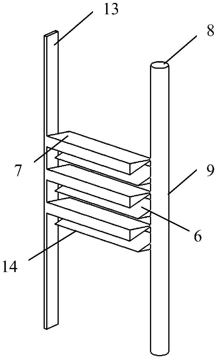
[0043] like image 3 and 4 As shown, the difference between this embodiment and Embodiment 1 is only the shape of the stirring paddle and the baffle. Taking one side of the rotating shaft as an example, the stirring paddle 6 in this embodiment includes two horizontal support rods 15, two A plurality of paddles 16 are radially arranged on the support rods, and the paddles on the two support rods extend axially toward each other.
[0044] As far as a single paddle is concerned, it is thin-plate-shaped, and the plate surface is approximately vertical and consistent with the radial direction of the rotating shaft. is 45°, and the other acute angle points to the axis of rotation.
[0045] The baffle plate cooperating with the stirring paddle is located in the middle of the two support rods. As shown in the figure, the baffle plate includes a radially extending support portion 17, and several baffle plates 18 are arranged on the top and bottom of the support portion 17, each The ...
Embodiment 3
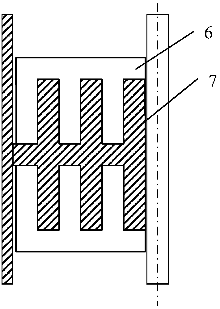
[0049] like Figure 5 and 6 As shown, the difference between this embodiment and Embodiment 1 lies in the shape of the stirring paddle and the baffle plate. Part 21, the third transverse part 22, and the vertical part 23 connecting the three, wherein the first transverse part 20 in the middle is connected with the shaft sleeve, and the vertical part 23 is close to the inner wall 13 of the straight tube section.
[0050] The first transverse portion 20, the second transverse portion 21, and the longitudinal section of the third transverse portion 22 are all right-angled triangles. Taking the first transverse portion 20 as an example, an acute angle thereof is used as the shearing edge 14, and the cutting edge angle is 60°. The shearing edge 14 points to the rotation direction of the stirring paddle, and the same is true for the shearing edges on the second transverse portion 21 and the third transverse portion 22 .
[0051] The baffle plate 7 cooperating with the stirring pad...
PUM
| Property | Measurement | Unit |
|---|---|---|
| Edge angle | aaaaa | aaaaa |
| Edge angle | aaaaa | aaaaa |
Abstract
Description
Claims
Application Information
 - R&D Engineer
- R&D Manager
- IP Professional
- Industry Leading Data Capabilities
- Powerful AI technology
- Patent DNA Extraction
Browse by: Latest US Patents, China's latest patents, Technical Efficacy Thesaurus, Application Domain, Technology Topic.
© 2024 PatSnap. All rights reserved.Legal|Privacy policy|Modern Slavery Act Transparency Statement|Sitemap