End face driven gear hobbing clamp

A technology of gear fixture and driving roller, applied in the direction of gear tooth manufacturing device, belt/chain/gear, gear tooth, etc., can solve the difficulty of loading and unloading the workpiece gear, the poor consistency of the workpiece gear accuracy, and the easy pulling of the inner hole of the workpiece gear. damage and other problems, to meet the requirements of high-precision machining and mass production, high machining accuracy, easy and fast clamping and unloading

Inactive Publication Date: 2014-03-19
WUXI WEIFU CHINA ITAL GEAR
View PDF7 Cites 4 Cited by
  • Summary
  • Abstract
  • Description
  • Claims
  • Application Information

AI Technical Summary

Problems solved by technology

However, when the gap between the inner hole of the workpiece gear and the mandrel is too small, it is difficult to put in and take out the workpiece gear, and it is easy to scratch the surface of the inner hole of the workpiece gear, thereby affecting the accuracy of the mandrel.
Therefore, the traditional mandrel-type fixture has problems such as inconvenient operation, poor consistency of workpiece gear accuracy, and easy straining of the inner hole of the workpiece gear.

Method used


Image

  • End face driven gear hobbing clamp
  • End face driven gear hobbing clamp
  • End face driven gear hobbing clamp

Examples


Embodiment Construction

[0015] The present invention will be further described below in conjunction with specific drawings and embodiments.

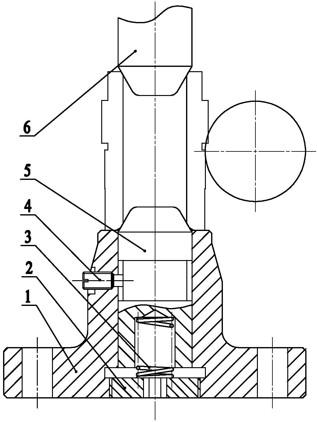
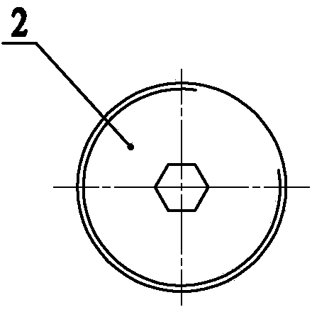
[0016] As shown in the figure: the end face driving roller gear fixture in the embodiment is mainly composed of a base 1, an adjusting nut 2, a strong spring 3, a top screw 4 and a floating center 5 and other components.

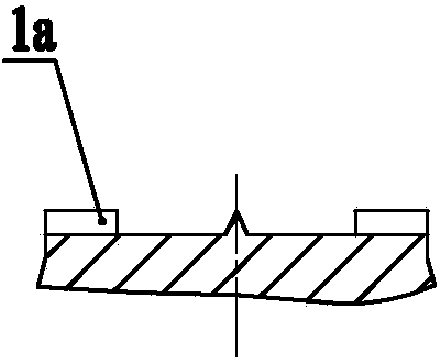
[0017] Such as figure 1 , the top of the base 1 is provided with circumferentially evenly distributed end pawls 1a, and the center of the base 1 is provided with a mounting hole, the strong spring 3 and the floating top 5 are installed in the mounting holes on the base 1, and the upper end of the strong spring 3 withstands the floating The top 5 and the lower end of the powerful spring 3 are supported on the adjustment nut 2, and the adjustment nut 2 is threaded in the installation hole; the top wire 4 radially penetrates the outer wall of the base 1, and the inner end of the top wire 4 is embedded in the shaft on the outer peripheral wall o...


PUM


Abstract

The invention relates to an end face driven gear hobbing clamp. The end face driven gear hobbing clamp is characterized by comprising a base, an adjusting nut, a powerful spring, a jackscrew and a floating tip, wherein end face pawls evenly distributed circumferentially are arranged at the top of the base, an installing hole is formed in the center of the base, the powerful spring and the floating tip are installed in the installing hole in the base, the upper end of the powerful spring abuts against the floating tip, the lower end of the powerful spring is supported on the adjusting nut, and the adjusting nut is connected in the installing hole in a threaded mode. The jackscrew radially penetrates the outer wall of the base, the inner end of the jackscrew is embedded into an axial long groove in the peripheral wall of the floating tip, and the jackscrew can prevent the floating tip from bouncing out or falling and limit rotation of the floating tip. The end face driven gear hobbing clamp is simple in structure, simple and convenient to operate, quick, efficient, good in reliability and capable of achieving quick and accurate gear centering and meeting high-accuracy gear machining and batch production requirements.

Description

technical field [0001] The invention relates to a clamp used in gear hobbing processing, in particular to an end face driven rolling gear clamp, which belongs to the technical field of mechanical parts processing. Background technique [0002] In the gear hobbing process, the commonly used fixture is the mandrel type, that is, the inner hole of the workpiece gear is used for positioning, and the mandrel is fixed on the workbench. However, the clamping workload of this fixture is large, and the workpiece gear needs to be loaded and taken out on the mandrel, which is inconvenient to operate. At the same time, the clearance between the mandrel and the inner hole of the workpiece gear is relatively strict, otherwise the hobbing accuracy and consistency of the workpiece gear will be affected, so it is necessary to control the clearance between the inner hole of the workpiece gear and the mandrel. But when the gap between the inner hole of the workpiece gear and the mandrel is to...

Claims


Application Information

Patent Timeline
Patent Type & Authority Applications(China)
IPC IPC(8): B23F23/06
Inventor 许智慧高友生
Owner WUXI WEIFU CHINA ITAL GEAR
Why Eureka
Try Eureka