
Automatic welding machine for automobile shock absorber cover

An automatic welding machine, automobile shock absorber technology, applied in welding equipment, welding equipment, auxiliary welding equipment, etc., can solve the problems of uneven welding points, large power grid power impulse, affecting the appearance of workpieces, etc., to avoid The effect of heat aging, reducing labor intensity and improving work efficiency

Active Publication Date: 2014-03-19
TIANJIN JINRONG TIANYU PRECISION MACHINERY CO LTD
View PDF8 Cites 4 Cited by
  • Summary
  • Abstract
  • Description
  • Claims
  • Application Information

AI Technical Summary

Problems solved by technology

[0002] There are two processes for welding automobile shock absorber covers. One is that there are bumps on the shock absorber cover. When welding, the two parts are welded together by bump welding. The other process is single-point resistance welding. These two processes Each has its advantages and disadvantages. The first type of welding requires the upper and lower electrodes to be relatively flat, and the adjustment accuracy of the tooling welding plane is high. During welding, the power requirements of the welding machine tool are large, and the instantaneous impulse of the power grid is large. After welding, the welding force of each point is inconsistent.
The second welding process is point-by-point welding. The power requirement of the welding machine is small, and the welding force of each point is even. The process generally needs to be welded 6 times, and the welding efficiency is significantly reduced. Manually rotating the workpiece results in uneven distribution of the 6 solder joints, which affects the appearance of the workpiece.

Method used


Image

  • Automatic welding machine for automobile shock absorber cover
  • Automatic welding machine for automobile shock absorber cover
  • Automatic welding machine for automobile shock absorber cover

Examples


Embodiment Construction

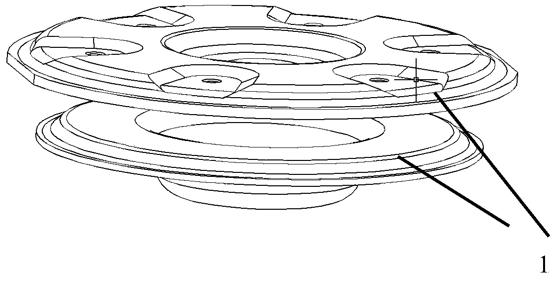
[0018] This automatic welding machine for automobile shock absorber cover is to weld automobile shock absorber cover (such as figure 1 Shown) The two single pieces are welded together with a solder mask machine.

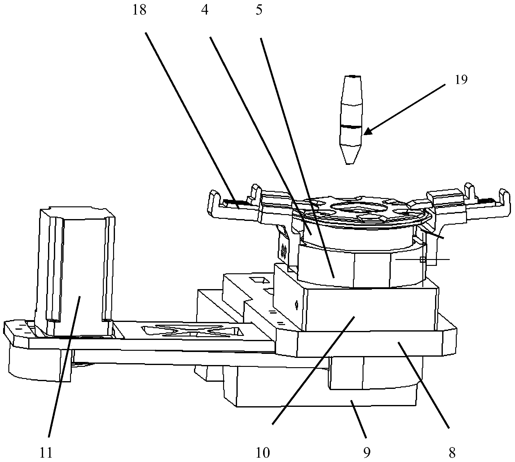
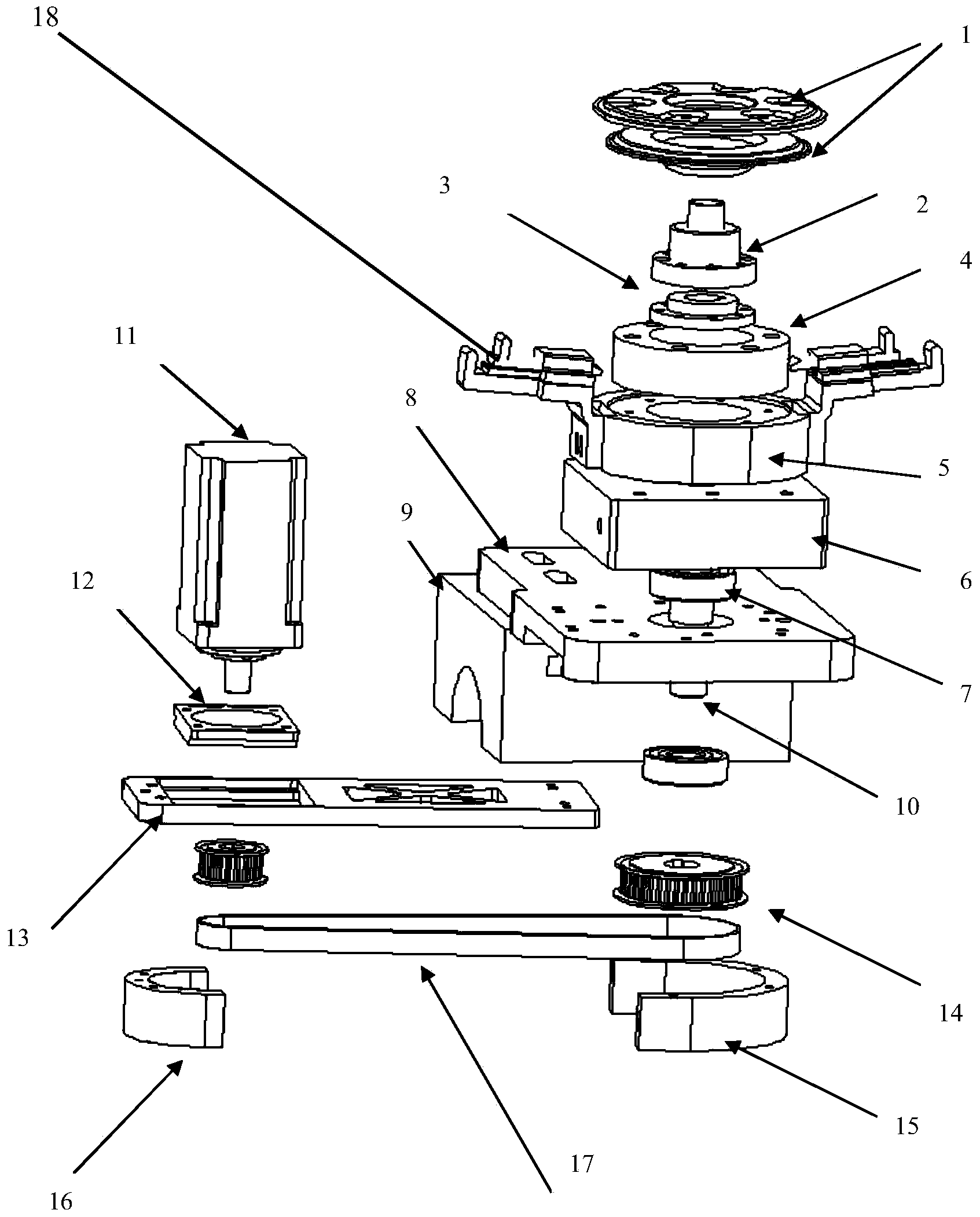
[0019] Such as figure 2 , 3 An automatic welding machine for automobile shock absorber cover is shown, which is composed of a servo motor on the left and a welding electrode on the right. The welding machine supporting plate is installed on the lower electrode of the resistance welding machine, the servo motor fixing frame is connected under the welding machine supporting plate, the electrode cooling block is installed on the welding machine supporting plate, the electrode rotating tire is installed on the electrode cooling block, and the electrode rotating tire is above Equipped with welding lower electrode, welding machine support plate, electrode cooling block, electrode rotating tire and welding lower electrode are on the same axis, welding machine supporting ...


PUM


Abstract

The invention discloses an automatic welding machine for an automobile shock absorber cover; a welding machine supporting plate is mounted on a welding blocking machine bottom electrode; a servo motor fixing bracket is connected with the lower surface of the welding machine supporting plate; an electrode heat dissipation block is mounted on the welding machine supporting plate; an electrode rotary tyre is mounted on the electrode heat dissipation block; a welding lower electrode is mounted on the electrode rotary tyre; a center hole is formed in the welding machine supporting plate, the electrode heat dissipation block, the electrode rotary tyre and the welding lower electrode in a penetrating manner; a workpiece fixing ring is arranged in the upper end of the center hole; the lower end of the workpiece fixing ring is connected with a connecting flange; a welding rotating shaft is connected with the lower side of the connecting flange; the lower end of the welding rotating shaft penetrates through the center hole of the welding machine supporting plate; a tooth type belt wheel is mounted at the lower end of the welding rotating shaft; a tooth type belt wheel on a servo electrode is connected with the tooth type belt wheel at the lower end of the welding rotating shaft through a tooth type belt; casting die claw mechanisms are mounted on the outer sides of the electrode rotary tyre. The welding machine can carry out one time card mounting and continuous welding, the work efficiency is improved, the labor intensity of operation workers is relieved, the workpiece has no difference after being welded, and the production efficiency is one workpiece per 15 seconds.

Description

technical field [0001] The invention belongs to automatic welding equipment for mechanical products, in particular to an automatic welding machine for automobile shock absorber covers. Background technique [0002] There are two processes for welding automobile shock absorber covers. One is that there are bumps on the shock absorber cover. When welding, the two parts are welded together by bump welding. The other process is single-point resistance welding. These two processes Each has its advantages and disadvantages. The first type of welding requires the upper and lower electrodes to be relatively flat, and the adjustment accuracy of the tooling welding plane is high. During welding, the power requirements of the welding machine tool are large, and the instantaneous impulse of the power grid is large. After welding, the welding force of each point is inconsistent. The second welding process is point-by-point welding. The power requirement of the welding machine is small, a...

Claims


Application Information

Patent Timeline
IPC IPC(8): B23K11/11B23K11/36
CPCB23K11/115B23K11/36B23K37/003B23K37/0435
Inventor 刘平
Owner TIANJIN JINRONG TIANYU PRECISION MACHINERY CO LTD
Learn More