Spring grinding machine

A technology of spring grinding machine and motor pump, applied in the field of grinding spring machinery and spring grinding machine, can solve the problems of good cooling effect, increase of spring temperature, no cooling time, etc., to avoid stability decline, prevent clogging, The effect of reducing investment costs

Inactive Publication Date: 2014-03-19
ZHUJI GUANGXIN AUTOMATION EQUIP
View PDF4 Cites 6 Cited by
  • Summary
  • Abstract
  • Description
  • Claims
  • Application Information

AI Technical Summary

Problems solved by technology

[0005] In order to reduce the temperature of the spring during the grinding process, liquid circulation is generally used for cooling. Due to the spring grinding process in the prior art, one is that the spring fixing seat remains in the original position, and the grinding machine moves forward for grinding. The spring fixed seat moves forward, and the grinding machine keeps the original position for grinding. In these two methods, the end face and the grinding wheel of the spring grinding are kept

Method used


Image

  • Spring grinding machine
  • Spring grinding machine
  • Spring grinding machine

Examples


Embodiment Construction

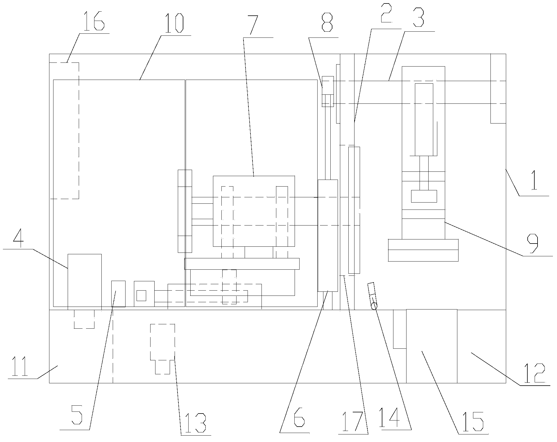
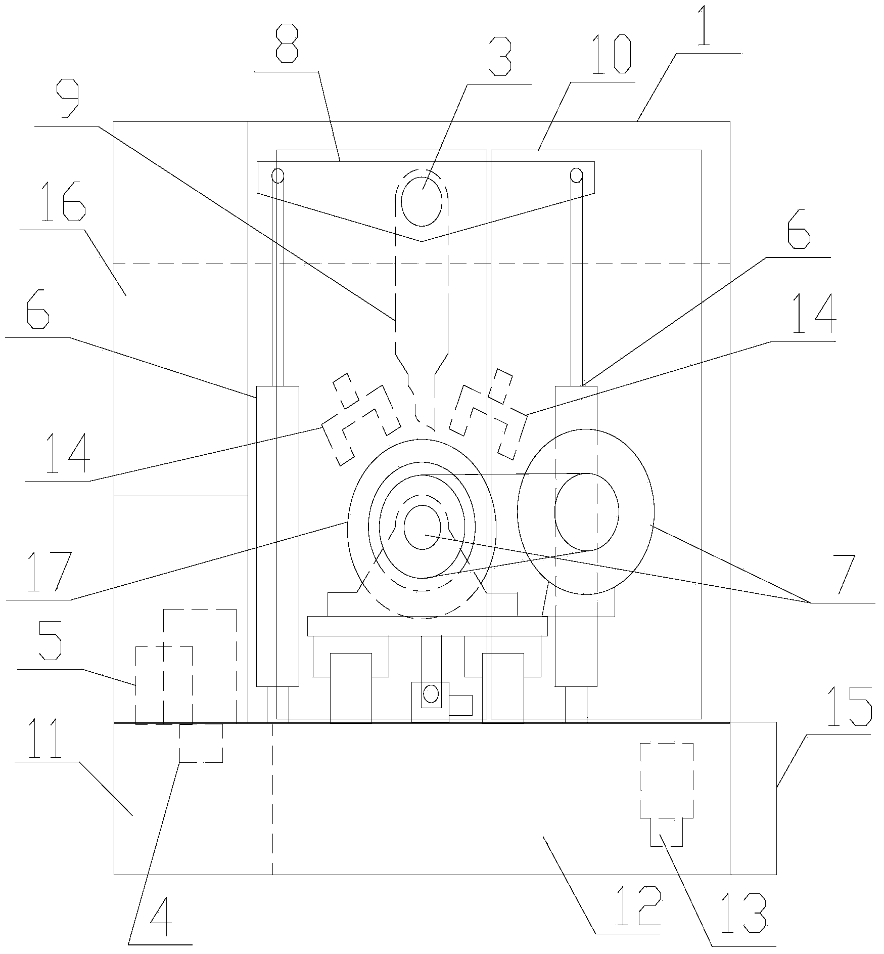
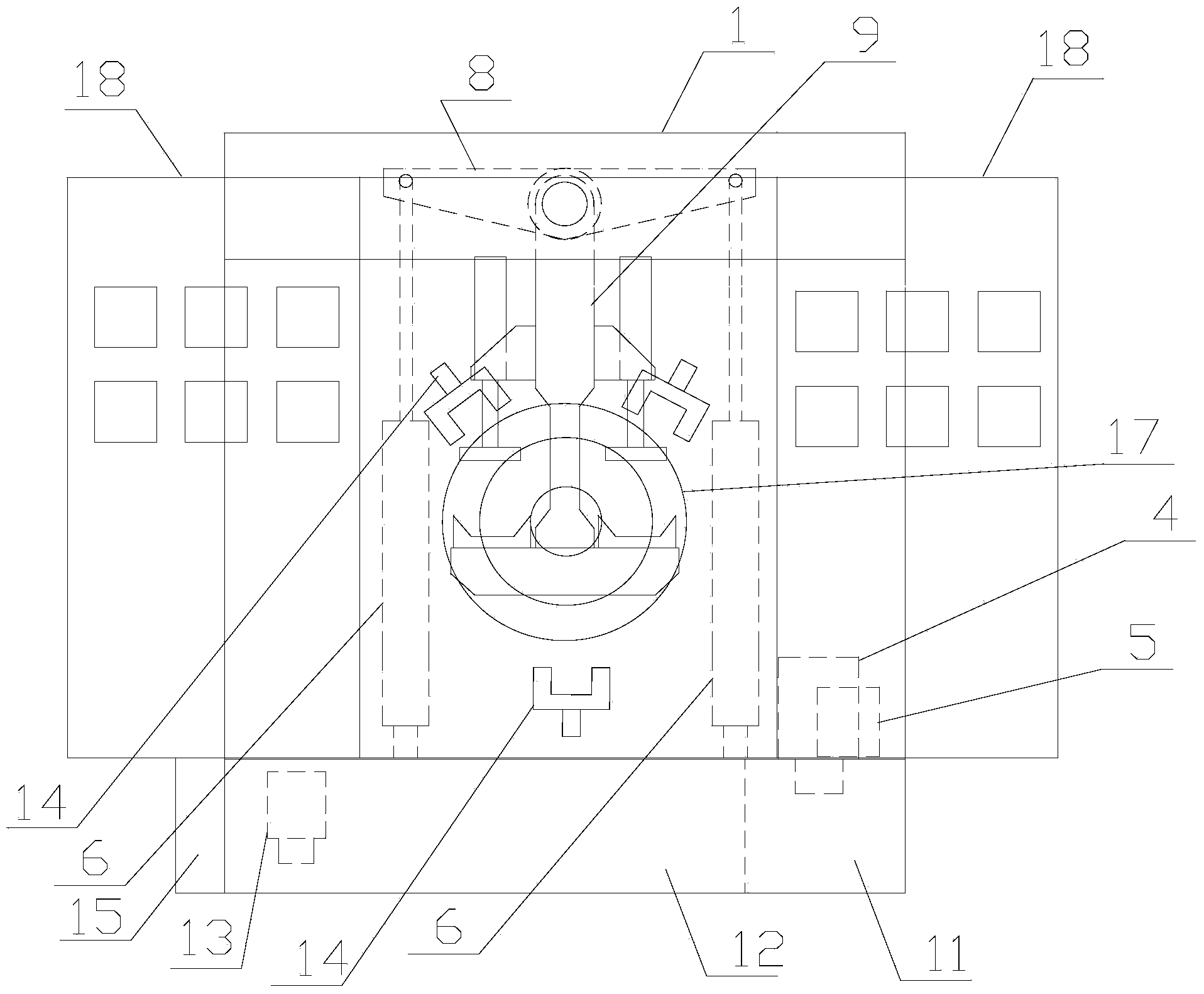
[0030] refer to figure 1 , figure 2 , image 3 , Figure 4 , Figure 5 and Figure 6 , a spring grinding machine of the present invention, comprising a first frame body 1, a partition plate 2, a connecting shaft 3, a first motor pump group 4, a valve group 5, a first hydraulic cylinder 6, a grinder device 7, a connecting arm 8, Support seat 9, protective door 10, oil tank 11, water tank 12, second motor pump group 13, water spray port 14, wear debris separation device 15, electrical box 16 and through hole 17, the input of the first motor pump group 4 The output end of the first motor pump group 4 is connected to the input end of the valve group 5, the output end of the valve group 5 is connected to the first hydraulic cylinder 6, and the input end of the second motor pump group 13 connected to the water tank 12, the output end of the second motor pump unit 13 is connected to the water spray port 14, the first frame body 1 is supported on the oil tank 11 and the water ta...


PUM


Abstract

The invention discloses a spring grinding machine. The spring grinding machine comprises a first frame body, a partition board, a connecting shaft, a first motor pump set, a valve set, a first hydraulic cylinder, a grinding machine device, a connecting arm, a support base, a protection door, an oil tank, a water tank, a second motor pump set, a water injection nozzle, an abrasive dust separating device, an electric appliance cabinet and a through hole, wherein the input end of the first motor pump set is connected with the oil tank, the output end of the first motor pump set is connected with the input end of the valve set, the output end of the valve set is connected to the first hydraulic cylinder, the input end of the second motor pump is connected with the water tank, the output end of the second motor pump set is connected with the water injection nozzle, the first frame body is supported by the oil tank and the water tank, the abrasive dust separating device is arranged on the side face of the water tank, the partition board, the grinding machine device and the water injection nozzle are arranged inside the first frame body, the partition board is provided with the connecting shaft, the through hole and the water injection nozzle, the connecting arm and the support base are arranged on the connecting shaft, a piston rod of the first hydraulic cylinder is connected with the connecting arm in a rotary mode, and the protection door and the electric appliance cabinet are arranged on the first frame body.

Description

【Technical field】 [0001] The invention relates to the technical field of spring grinding machines, in particular to the technical field of spring grinding machines. 【Background technique】 [0002] Generally, due to the shape of the spring, the two ends of the spring will be slightly raised and there will be more uneven material. However, some spring applications require the two ends of the spring to be relatively flat, so that the two ends of the spring and The contact area between the placement surfaces increases, thereby promoting the stability of the positioning, that is, the so-called straight angle of the end face needs to be relatively flat, so a spring grinder must be used to grind and smooth both ends of the spring. [0003] In the prior art, the supporting liquid cooling system, hydraulic system and grinding device on the spring grinding machine are all separately placed on the production site, which creates a certain distance between the liquid cooling system, hydr...

Claims


Application Information

Patent Timeline
IPC IPC(8): B24B7/17B24B55/02B24B55/06
CPCB24B7/167B24B7/17B24B55/02B24B55/06
Inventor 刘仲良
Owner ZHUJI GUANGXIN AUTOMATION EQUIP
Why Eureka
Try Eureka