Reinforced deep-denitrifying device with multi-point water-inflow coupling fixed film

A technology that strengthens deep and multi-point water inflow, which is applied in the field of denitrification devices, deep denitrification, and multi-point water inflow coupling fixed film enhanced deep denitrification devices. Limitation, complex control structure and other issues, to achieve the effect of improving TN removal rate, saving land occupation, and strengthening denitrification effect

Active Publication Date: 2014-03-19
HEILONGJIANG INST OF TECH
View PDF5 Cites 2 Cited by
  • Summary
  • Abstract
  • Description
  • Claims
  • Application Information

AI Technical Summary

Problems solved by technology

[0005] The purpose of the present invention is to solve the problems of limited total nitrogen removal rate caused by the structural limitation of the existing segmented water inflow A / O process; complex process, large area occupation, high infrastructure investment; high requirements for deep denitrification control and complex control structure

Method used


Image

  • Reinforced deep-denitrifying device with multi-point water-inflow coupling fixed film

Examples


specific Embodiment approach 1

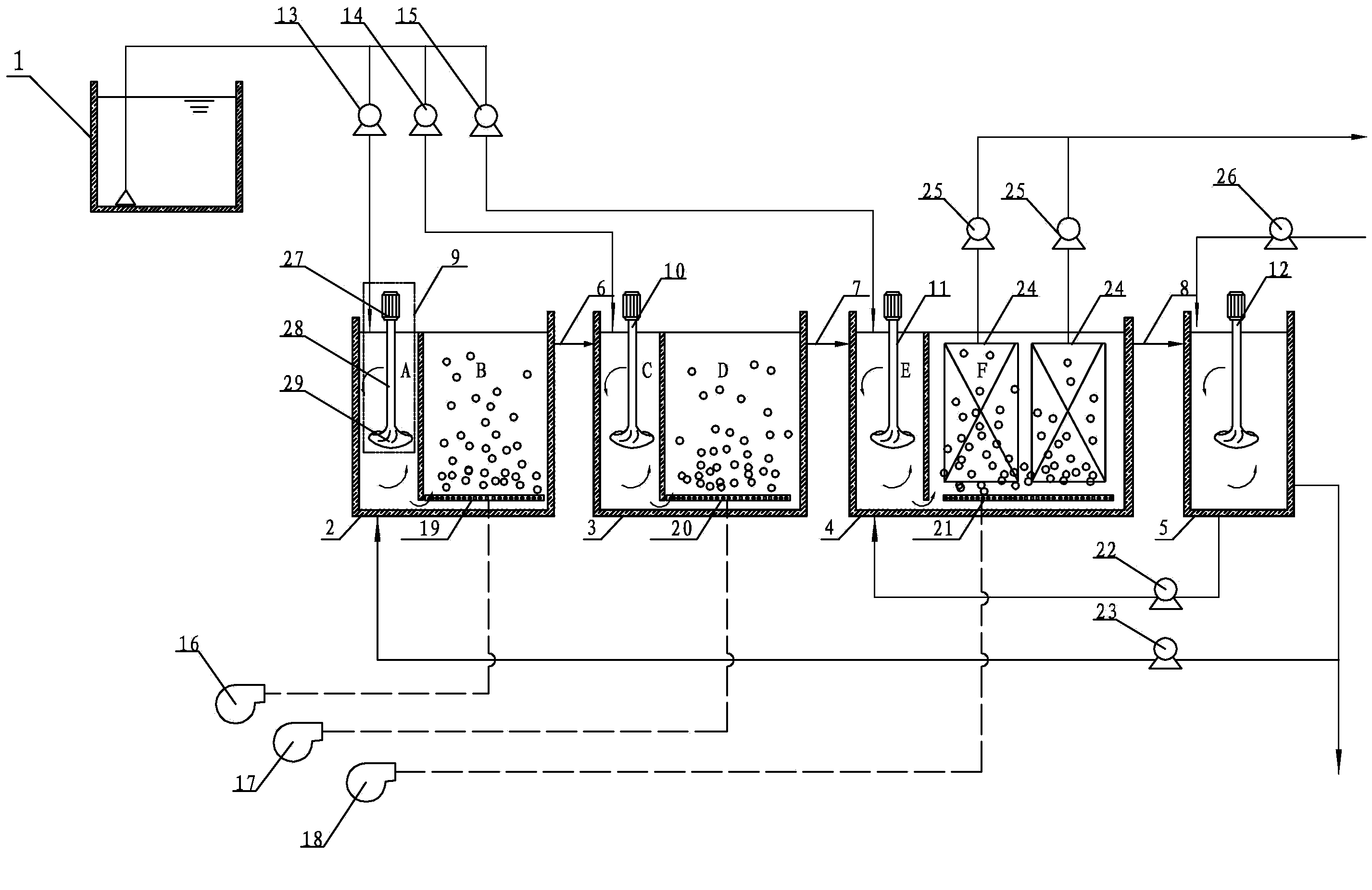
[0015] Specific implementation mode one: combine figure 1 Describe this embodiment. This embodiment includes a flow regulating tank 1, a first-stage water inlet flow pump 13, a second-stage water inlet flow pump 14, a first-stage main body structure 2, a second-stage structure 3, and a first-stage mechanical stirring device 9 , The second section of mechanical stirring device 10, the first section of aerobic zone aeration pipe 19, the second section of aerobic zone aeration tube 20, the first section of aerobic zone gas supply device 16, the second section of aerobic zone gas supply The device 17 and the first section of the water outlet pipe 6, the flow regulating pool 1, the first section of the main structure 2 and the second section of the structure 3 are arranged in sequence from left to right, and the inside of the first section of the main structure 2 is divided into the first anoxic zone by a partition A and the first aerobic zone B, and the lower part of the first ano...

specific Embodiment approach 2

[0017] Specific implementation mode two: combination figure 1Describe the present embodiment, the first stage mechanical stirring device 9 of the present embodiment, the second stage mechanical stirring device 10, the 3rd mechanical stirring device 11, the post anoxic zone mechanical stirring device 12 all comprise motor 27, stirring shaft 28 and The stirring paddle 29, the motor 27, the stirring shaft 28 and the stirring paddle 29 are connected sequentially from top to bottom. With such arrangement, the structure is simple and the stirring effect is good. Other compositions and connections are the same as in the first embodiment.

specific Embodiment approach 3

[0018] Specific implementation mode three: combination figure 1 Describe this embodiment, the bottom end face of the partition wall in the first section of the main structure 2, the second section of the structure 3 and the third section of the main structure 4 of this embodiment is provided with a water outlet, the water outlet is a square, and the determination of the area is based on daily The maximum and minimum water inflow flow rate is guaranteed to be 0.8m / s~2.5m / s. Such setting makes the mixing of pollutants and activated sludge more complete, and facilitates the formation of plug flow mode. Other compositions and connections are the same as in the first embodiment.

[0019] Specific implementation mode four: combination figure 1 Describe this embodiment, the aeration pipe 19 of the first section of the aerobic zone, the aeration pipe 20 of the second section of the aerobic zone and the aeration pipe 21 of the third section of the aerobic zone of this embodiment are ...


PUM

PropertyMeasurementUnit
pore sizeaaaaaaaaaa
areaaaaaaaaaaa

Abstract

The invention discloses a reinforced deep-denitrifying device with a multi-point water-inflow coupling fixed film and relates to a denitrifying device, which aims at solving the problem that total nitrogen removing rate is limited by an existing stepped water-inflow A(Anoxic / O(Oxic) process, flow is complex, floor space is large, capital investment is high, deep-denitrifying control requirements are high and a control structure is complex. A flow rate regulating tank, a first-section main body structure and a second-section structure are arranged in sequence from the left to the right; a first-section mechanical stirring device and a second-section mechanical stirring device are respectively arranged in a first anoxic area and a second anoxic area, respectively; a first-section aerobic aeration area tube and a second-section aerobic area aeration tube are respectively arranged in a first aerobic area and a second aerobic area; a third-section main body structure and a rear anoxic tank are arranged in sequence from the left to the right; a third mechanical stirring device is arranged in a third anoxic zone; a rear anoxic area mechanical stirring device is arranged in the rear anoxic tank. The reinforced deep-denitrifying device disclosed by the invention is used for deep denitrifying of domestic wastewater and nitrogen-containing industrial wastewater of medium and small cities and towns.

Description

technical field [0001] The present invention relates to a denitrification device, in particular to a multi-point water inlet coupling fixed membrane enhanced deep denitrification device for nitrogen-containing wastewater, which belongs to the field of advanced sewage treatment, and is especially suitable for medium and small urban domestic sewage and nitrogen-containing industrial wastewater deep denitrification. Background technique [0002] The problem of eutrophication is one of the most important water pollution problems faced by countries all over the world. Although the treatment rate of urban sewage in my country has been continuously improved in recent years, the problem of eutrophication caused by nitrogen and phosphorus pollution has not been fundamentally solved. There is even a growing trend. my country's large freshwater lakes and coastal waters are moderately or severely polluted with eutrophication. In the newly promulgated "Pollutant Discharge Standards for ...

Claims


Application Information

Patent Timeline
Patent Type & Authority Applications(China)
IPC IPC(8): C02F3/30
Inventor 王伟邵纯红张鑫刘丽娜
Owner HEILONGJIANG INST OF TECH
Why Eureka
Try Eureka