Time grating linear displacement sensor

A technology of linear displacement and sensors, applied in the direction of instruments, measuring devices, electrical devices, etc., can solve the problems of high cost and achieve the effects of low cost, improved resolution and simple structure

Inactive Publication Date: 2014-03-19
CHONGQING UNIV OF TECH
View PDF6 Cites 35 Cited by
  • Summary
  • Abstract
  • Description
  • Claims
  • Application Information

AI Technical Summary

Problems solved by technology

The time grating linear displacement sensor is mainly based on the principle of electromagnetic induction, and its resolution is not only determined by the space equivalent of the interpolation clock pulse, but also proportional to the periodic pitch of the sensor. For example, a linear displacement sensor disclosed in CN102359753A, when its interpolation After the space equivalent of the complementary clock pulse reaches a certain limit, if you want to further improve its resolution, you can only achieve it by further increasing the periodic pitch of the sensor or complex electronic subdivision, which is expensive

Method used


Image

  • Time grating linear displacement sensor
  • Time grating linear displacement sensor
  • Time grating linear displacement sensor

Examples


Embodiment 1

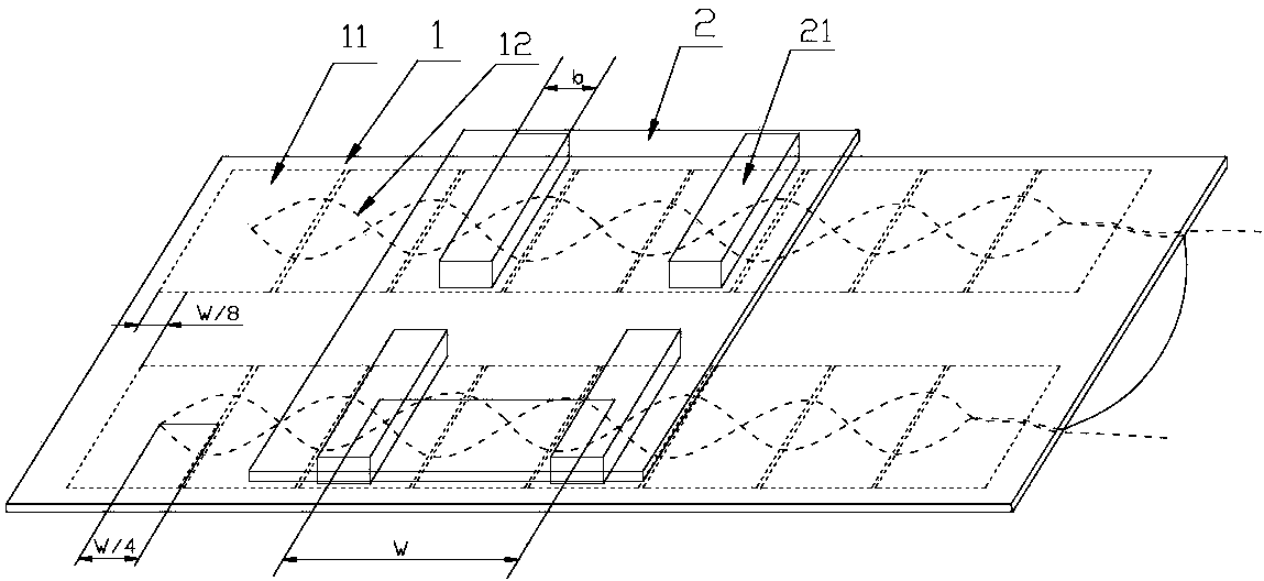
[0023] Embodiment 1: as figure 1 , Figure 4 , Figure 5 The time grating linear displacement sensor shown includes fixed scale 1 and moving scale 2.

[0024] The fixed length 1 is composed of a rectangular parallelepiped fixed length substrate and two identical and parallel sensing units arranged on the upper and lower parts of the fixed length substrate. The fixed length substrate adopts the printed circuit board substrate, and the length of the fixed length substrate is The side direction is the measurement direction, and each sensing unit includes an excitation coil 11 and an induction coil 12 .

[0025] The excitation coil 11 is composed of four positively wound planar rectangular spiral excitation coils 111 and four reversely wound planar rectangular spiral excitation coils 112 arranged alternately along the measurement direction, and arranged on the same wiring layer. The forwardly wound planar rectangular spiral excitation coils 111 and The size of the anti-winding ...

Embodiment 2

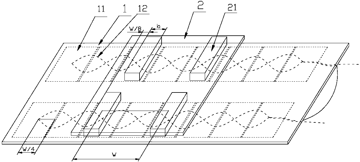
[0038] Embodiment 2: as figure 2 , Figure 4 , Figure 5 The structure of the time grating linear displacement sensor shown is mostly the same as that of Embodiment 1, except that the initial position of the sensing unit arranged on the upper part of the fixed-length base is the same as that of the sensing unit arranged on the lower part of the fixed-length base. The initial position is aligned, and the initial position of the magnetic conductor 21 embedded in the magnetic permeable unit at the upper part of the moving scale base is different from the initial position of the magnetic permeable body 21 embedded in the magnetic permeable unit at the lower part of the movable scale base

[0039] The excitation coils of the upper and lower sensing units of fixed length 1 are respectively connected with sinusoidal excitation currents with the same two-phase amplitude and a phase difference of 180°, and the induction coils of the upper and lower sensing units will respectively g...

Embodiment 3

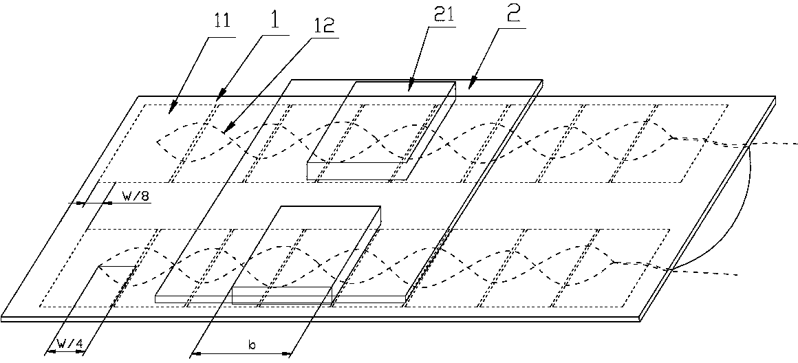
[0046] Embodiment 3: as image 3 , Figure 4 , Figure 5 The time grating linear displacement sensor shown, most of its structure is the same as that of embodiment 1, the difference is that: the magnetic conduction unit of moving ruler 2 is made of a rectangular parallelepiped magnetic conductor 21, and along the measurement direction, the magnetic conductor The width b of 21 is equal to

[0047] The excitation coils of the upper and lower sensing units of fixed length 1 are respectively connected with sinusoidal excitation currents with the same two-phase amplitude and a phase difference of 180°, and the induction coils of the upper and lower sensing units will respectively generate formula (7) And the induction signal of formula (8):

[0048] e 1 = K 3 sin 2 π t T sin ( 2 π ...


PUM


Abstract

The invention discloses a time grating linear displacement sensor. The time grating linear displacement sensor comprises a fixed ruler and a movable ruler, wherein the fixed ruler is composed of a fixed ruler base body and two same and parallel sensor units arranged on the upper portion and the lower portion of the fixed ruler base body, wherein each sensor unit comprises exciting coil and induction coils. The exciting coils are formed by sequentially arranging a plurality of forward-wound plane rectangular spiral exciting coils and a plurality of reverse-wound plane rectangular spiral exciting coils along a measurement direction in a staggered mode, and the exciting coils can generate a magnetic field which changes according to sine rules. The induction coils are formed by sequentially arranging a plurality of forward-wound induction coils and a plurality of reverse-wound induction coils along the measurement direction in a staggered mode. The movable ruler and the fixed ruler generate relative movement along the measurement direction, the induction coils which are connected in series in the sensor units together output induction signals of constant amplitudes, phase demodulation processing and high frequency clock pulse interpolation are performed on the induction signals and excitation signals, and linear displacement is obtained after conversion. The time grating linear displacement sensor can double the resolving power of the time grating linear displacement sensor under the condition that the degree of precision of scale marks is not increased.

Description

technical field [0001] The invention belongs to the technical field of precision measurement sensors, and in particular relates to a time grating linear displacement sensor. Background technique [0002] Linear displacement measurement is the most basic geometric quantity measurement. Precision linear displacement measurement mainly uses linear displacement sensors, such as gratings, magnetic gratings, capacitive gratings, etc., which obtain the displacement by counting the grid lines divided by space. Their common feature is to use the space ultra-precise scribe line of the grid line to meet the resolution requirements of small displacements. In order to further improve the resolution, they can only rely on complex electronic subdivision, which makes the system structure complicated and the cost high. And the anti-interference ability is poor, and it is very easy to be polluted. [0003] In recent years, a time grating linear displacement sensor with clock pulse as the mea...

Claims


Application Information

Patent Timeline
Patent Type & Authority Applications(China)
IPC IPC(8): G01B7/02
Inventor 鲁进彭东林陈锡侯武亮汤其富孙世政
Owner CHONGQING UNIV OF TECH
Why Eureka
Try Eureka